Guide H-331
Bernd Maier
College of Agricultural, Consumer and Environmental Sciences, New Mexico State University
Author: Extension Viticulture Specialist, Department of Extension Plant Sciences, New Mexico State University. (Print Friendly PDF)
Introduction
Proper construction and installation of the vineyard trellis are important components in the establishment and success of a vineyard. The trellis is the main support structure of grape vines in the vineyard; it must be sturdy enough to support canopy and wind loads that exert forces on the catch and cordon wires, line posts, and end assemblies. The vineyard trellis, and especially the end post assembly, must be properly constructed to support canopy and wind loads. The mechanics of the end post assembly involve simple physics. Cordon and catch wires support the grape vines. The end post assemblies at the end of each row anchor these wires. The weight from the vines and fruit exert a downward force (tension) on the wires. Tension from the trellis wires transfers to the end posts. This force, along with resistance between the end post and the soil, keeps the post in place and prevents the trellis wires from sagging. Improperly installed end posts can bend and/or pull through the soil, causing the trellis wires to sag.
Two styles of end post assemblies are used in vineyards: the anchored end post assembly (Figure 1) and the H-brace end post assembly (Figure 2). Some factors to consider when deciding which assembly will work best include material and equipment availability, vineyard design, soil type, and cost of materials and labor. For example, if space is limited at the head rows, the H-brace assembly is preferred in order to avoid a collision between the end posts and mechanized equipment. However, if cost is a significant factor, the H-brace assembly may not be the most appropriate because it requires extra materials and labor during installation compared to the anchored end post assembly. If needed, there are consultants who can assist in determining which end post assembly is better when establishing a vineyard. Still, no matter which end post assembly is chosen, the correct installation is crucial for proper function.
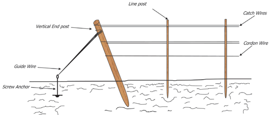
Figure 1. Anchored end post assembly. (All drawings not to scale.)
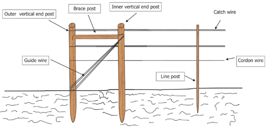
Figure 2. H-brace end post assembly.
Materials for End Posts
Depending on the application and budget, many types of materials are available for an end post assembly. These include specific species of wood (e.g., cedar), pressure-treated wood, metal, and concrete. Again, careful consideration must be given when choosing which end post material is best.
When choosing a specific species of wood for an end post, make sure the wood came from the heartwood instead of the sapwood of the tree. Heartwood is the interior, nonliving harder wood that will be darker, denser, less permeable, and more durable than the surrounding sapwood. Sapwood is the younger, living outer portion that lies between the cambium and the heartwood and is lighter in color, softer, more permeable, and less durable. Review of literature has shown that the heartwood posts taken from trees such as cedar, Osage orange, and black locust have lasted 20 years or more. However, consider that many posts milled today from these same species only last 5 to 10 years because they are being harvested from secondary growth forests and do not have the same durability as wood taken from old-growth forests in past decades. When purchasing the posts, check that they have been fully seasoned. Posts not properly seasoned have a tendency to bend or warp. For these reasons, only purchase posts from reputable lumber dealers and avoid the temptation to purchase cut-rate posts.
Pressure-treated wood has also been used for end post assemblies in vineyards. Pressure treating is a process that forces chemicals such as chromium, copper, and arsenic deep into the wood. These chemicals, also known as chromated copper arsenate (CCA), act as a preservative and protect the posts from insect damage and fungal decay. However, research has shown that, over time, arsenic leaches from the pressure-treated wood into the soil and water sources. Another problem is that vineyards replacing pressure-treated (CCA) posts with environmentally friendly posts are having difficulties with disposal because of the toxicity to the environment.
The Environmental Protection Agency has now restricted the use of CCA in treating wood, and pressure-treated wood is now being processed with copper azole (CA) or amine copper quat (ACQ). Although CA- and ACQ-treated posts are safer than CCA-treated posts since there is no arsenic, they do not have the same longevity. Certified organic growers need to check the regulations before using any pressure-treated posts.
Metal posts can also be used as end post assemblies. Metal posts are becoming more cost-effective than wood posts over the long-term, particularly when labor, equipment, and material costs are considered in the final calculations. Another plus if using steel posts is that they are usually manufactured from salvaged steel and can also be recycled if replaced. Although metal post have the strength to handle canopy and wind loads, they do bend if hit by machinery. There is also a concern that metal posts will rust over time. Galvanizing metal posts helps prevent rust and prolongs the life of the post, and posts treated with polyester spray paint can prolong the post’s life for up to 30 years.
Finally, concrete posts are becoming popular in vineyards. They are moisture- and fungal-resistant and can last up to 30 years. Also available are pre-stressed concrete posts, which are reinforced with a patented “pre-stressed” wire. This makes the concrete post more sturdy and resilient than concrete posts with regular reinforced wire or steel.
Anchored End Post Assembly
The anchored end post assembly is the most commonly used assembly. The required materials are a vertical post 4 to 6 inches in diameter and 8 to 10 feet long, a screw anchor with a minimum plate diameter of 6 inches and vertical depth of 30 inches, and number 10 gauge galvanized wire.
Vertical post diameter and length will determine the tension strength of the assembly. To prevent the vertical post from bending under heavy loads, use larger-diameter posts (e.g., 5-inch diameter). In addition, the strength of the vertical post used in the anchored assembly varies in proportion to how deep the post is augered into the soil. The deeper the post, the greater the tension and the more weight the end assembly can support. Figure 3 illustrates the proper installation of an anchored end post assembly.
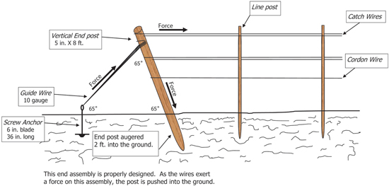
Figure 3. Proper installation of an anchored end post assembly.
The vertical end post should be augered into the ground at a 65° angle. At this angle, the tension from the trellis wires places pressure on the post, forcing it into the ground. Install the screw anchor approximately 4 feet away from the vertical post and approximately 30 inches deep in firm, undisturbed soil. This spacing allows the angle of the guide wire between the vertical post and screw anchor to be around 65°. In addition, the anchor’s shaft must be in line with the vertical end post and the start of the trellis wires. If not, the anchor shaft will bend or drag through the soil until in-line direction occurs between both.
To complete the end post assembly, number 10 gauge galvanized wire is used to connect the vertical post to the screw anchor. Fasten the guide wire to the anchor screw 3 inches above the soil and as close as possible to the catch wire on the end post. Again, this will help transfer the force from the tension of the trellis wires to the vertical end post. Finally, fasten the trellis wires to the vertical end post and not to the screw anchor.
Improperly installed end post assemblies prevent the force of the trellis wires from transferring to the vertical end post, thereby causing problems. For example, Figure 4 illustrates a vertical post augered in at 90° instead of 65°. The force now exerts tension toward the trellis wires and not against the end post and screw anchor, causing the weight from the canopy and wind load to pull the post out of the ground as shown in Figure 5. The result is sagging trellis wires that do not support the vines.
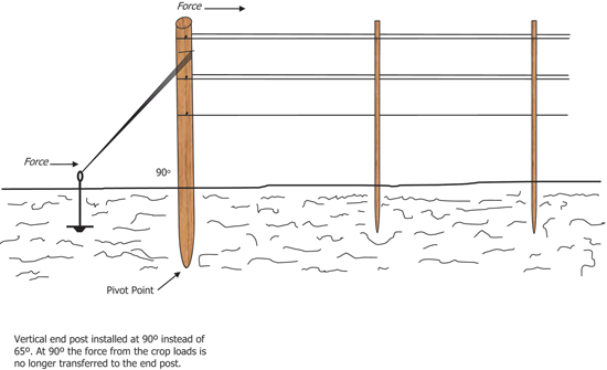
Figure 4. A vertical end post not properly installed at the correct angle.
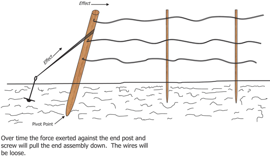
Figure 5. Force exerted against the end post and screw anchor, causing loose wires.
Another common mistake when installing the end post assembly is driving the anchor in at the wrong angle. The screw anchor should be driven straight into the soil so it is at a 90° angle to the soil surface. Figure 6 is an example of the proper way to put in an end post anchor. In this illustration, a wooden anchor stake is used instead of the screw anchor. Figure 7 demonstrates an incorrect installation angle of the wooden anchor stake. Not only is the anchor stake incorrectly installed, but the vertical end post is also improperly installed at 90°. When canopy or wind load forces are applied to the trellis wires, this force transfers to the end post or anchor stake. Now, instead of pulling the post into the ground, the force is applied using the post as a lever directly to the anchor, pulling the anchor up from the ground and loosening the trellis wires.

Figure 6. Proper installation of anchor stake and vertical end post.
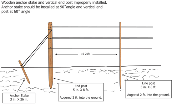
Figure 7. Improper installation of wooden anchor stake and vertical end post.
An alternative to the screw anchor is the “dead man” anchor. This type of anchor uses a reinforcement bar placed in concrete as shown in Figure 8. The reinforcement bar should be about 1 inch in diameter and approximately 4 feet long, and can be bent like the example in Figure 8. An eyehook is created at the top of the bar to attach the guide wire, and a 90° bend of 4 inches at the bottom will keep the bar in place. The reinforcement bar is placed in a 10-inch-wide by 40-inch-deep hole. The bottom 12 inches of the hole should be filled with concrete. The hole is then backfilled with soil and compacted. The soil on top of the concrete keeps the anchor in place when tension is applied to the trellis wires. If concrete is filled to the top of the hole as shown in Figure 9, there is no room left to backfill soil to hold the concrete in place. This can cause tension from the trellis wires to pull the concrete anchor out of the ground.
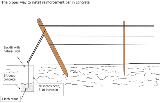
Figure 8. Proper installation of “dead man” anchor.
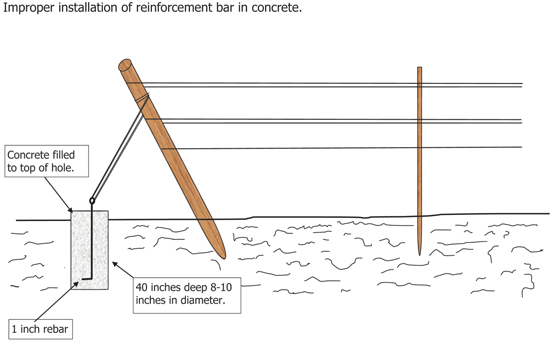
Figure 9. Improper way to install a “dead man” anchor for end posts.
H-Braced End Post Assembly
Utilize the H-brace end post assembly to avoid collisions with mechanized equipment when space is limited. Figure 10 illustrates an example of the H-brace end post assembly. Extra posts are required when installing this system. Two vertical wooden end posts approximately 5 inches in diameter and 8 feet long are augered at least 2 feet deep at the end of the rows. Back fill and firmly compact the soil around each post to prevent the post from pivoting when tension is applied to the trellis wires. A horizontal brace post is installed at the top between the two vertical posts, which braces the two posts. Use brace pins to connect the horizontal brace post to the vertical end post. Number 10 gauge guide wire tied between the top of the inner end post and the bottom of the outer end post provides extra support for posts. Finally, fasten the trellis wires to the top of the outer vertical post. All posts and guide wires should be in line with the start of the trellis wires. When tension occurs on the trellis wires, the inner post, brace post, and guide wire brace the outer post which in turns holds the brace assembly in place, preventing sag of the trellis wires.
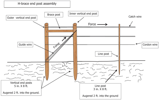
Figure 10. The proper way to install an H-brace end post assembly.
Conclusion
The anchored and H-braced end post assemblies can support vineyard trellises in a variety of situations. Factors such as material and equipment availability and costs, vineyard design, and soil type will determine which type of end post assembly is best for your vineyard. Regardless of which style you choose, the end post assemblies must be constructed and installed correctly to properly support the canopy and wind loads exerted on the trellis system.
References
Domoto, P. 2002. Constructing a vineyard trellis [Online]. Ames: Iowa State University.
Environmental Protection Agency. 2001. Preliminary evaluation of the non-dietary hazard and exposure to children from contact with chromated copper arsenate treated wood playground structures and contaminated soil [SAP Report No. 2001-12]. Washington, D.C.: Author.
Environmental Protection Agency. 2001. Sampling for residues of arsenic, chromium, and copper in substrates (soils/buffering materials) beneath/adjacent to chromated copper arsenate (pressure)-treated playground equipment. Washington, D.C.: Author.
Morrell, J.J., D.J. Miller, and P.F. Schneider. 1999. Service life of treated and untreated fence posts: 1996 post farm report [Research Contribution 26]. Corvallis: Oregon State University Forest Research Laboratory.
Zabadal, T. n.d. Engineering a modern vineyard trellis [Online]. East Lansing: Michigan State University.

Bernd Maier is the Extension Viticulture Specialist at New Mexico State University. He is a veteran of the New Mexico viticulture industry with over 25 years of experience in the state. His current research includes meteorological studies and remote sensing with respect to grape varieties for Northern and Southern New Mexico, trellis system and irrigation evaluation to enhance grape quality, and mechanization.
To find more resources for your business, home, or family, visit the College of Agricultural, Consumer and Environmental Sciences on the World Wide Web at pubs.nmsu.edu.
Contents of publications may be freely reproduced for educational purposes. All other rights reserved. For permission to use publications for other purposes, contact pubs@nmsu.edu or the authors listed on the publication.
New Mexico State University is an equal opportunity/affirmative action employer and educator. NMSU and the U.S. Department of Agriculture cooperating.
Printed and electronically distributed June 2012, Las Cruces, NM.