Circular 673
Thomas Jenkins and Gabriel Bolivar-Mendoza
College of Agricultural, Consumer and Environmental Sciences and College of Engineering, New Mexico State University
Authors: Respectively, Professor and Graduate Student, Department of Engineering Technology and Surveying Engineering, New Mexico State University. (Print friendly PDF)
Overview
This user manual and accompanying Microsoft Excel spreadsheet (https://pubs.nmsu.edu/_circulars/CR673/CR673.xlsm) are intended to be used as a guide through the basic process of designing a simple, stand-alone solar-powered lighting system (Figure 1), and to aid in feasibility and implementation decisions. The spreadsheet is designed to allow you to enter a variety of values, such as system location, number and type of lights, size of batteries, etc. By entering different values, you can investigate a variety of scenarios before making final implementation decisions.
There are NO expressed or implied guarantees with this system, nor is the spreadsheet/user manual intended to replace professional expertise. It is important to note that the system is designed using average wattage requirements of different types of lights. Values may vary, and this spreadsheet should ONLY be used as an educational tool.
The spreadsheet consists of different "sheets" or pages that are indexed via tabs at the bottom of the spreadsheet window. There is a title sheet, five sheets that represent the five main sequential steps in the design methodology, and a conclusion sheet (Figure 2). The currently selected sheet has a white background, and in Figure 1 this is the Title Page sheet.
On each sheet, there are different shaded boxes, areas, or spreadsheet cells. There are light-purple and light-blue shaded areas that are instructions and user notes that you should read when using each sheet. The green cells are where you can enter information. To enter a value, move the cursor and click on the green cell (or box), enter your value in that cell (typically a number), and press the "enter" or "return" key on your keyboard.
Some cells have a red triangle in their top right corner. When you place the cursor onto that cell, a "pop-up" note is displayed giving an additional short explanation related to that cell. Some cell entries are restricted in their allowable values. For example, the "Multiplier" cell in the Lights sheet (Figure 6) will only accept entries between 0—20. If you enter a value outside this range, an error message will be displayed and you must re-enter a valid value in this cell before continuing.
Some cells may also have a "drop-down" menu associated with them. A cell's menu can be accessed by placing the cursor on the cell and clicking on it. When this is done, a note is displayed and a drop-down menu tab is displayed to the right of the cell. When this tab is clicked, the drop-down menu displays the valid entries for this cell. Just move the cursor and click on any menu entry to make it the cell's input value.
Finally, orange boxes display intermediate values that are calculated by the spreadsheet, while yellow boxes show the final calculations in each design step, which are used in other calculations to generate the final design specifications.
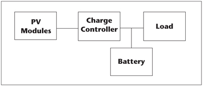
Figure 1. Typical standalone photovoltaic (PV) system block diagram.
Step-By-Step Design Procedure
Step 1. Determine Available Solar Resource
Begin by opening the spreadsheet and clicking on the Title Page sheet (the left-most tab at the bottom of the spreadsheet; see Figure 2). Read the title page material and view the internet video on solar lighting.
Next, continue to the first design sheet by clicking on the Solar Resource tab at the bottom of the spreadsheet (Figure 3). The purpose of this sheet is to determine the total daily insolation (i.e., sunlight) at a selected location. The sunlight on the solar panels provides the electricity to run the lights and charge the batteries. There are two green cell entries associated with this sheet: the state and the latitude in the state. First select the state—Arizona (AZ), New Mexico (NM), Colorado (CO), Utah (UT), or Nevada (NV)—by clicking on the green cell and using the state drop-down menu. Then, using the displayed map as an aid, enter the nearest latitudinal coordinate in the "Latitude" cell for your lights' location. For example, New Mexico and Arizona are located between latitudes 31 and 36°. A green highlight will appear on the state map indicating the latitude you have entered; Figure 4 shows an example in which 35° has been entered as the latitude for a location in New Mexico.
Photovoltaic (PV) panels are typically pointed due south and tilted at some angle from the horizontal to help capture the most sunlight (Figure 5). A rule of thumb for a fixed-tilt angle for all-year pumping is to tilt the PV at an angle equal to the site's latitude (35° in the case of the Albuquerque area). Single-axis solar "trackers" and two-axis trackers are devices that track or follow the sun as it moves from east to west during the day. Two-axis trackers also follow seasonal changes in the sun's path. Using a tracker can considerably increase the total solar energy absorbed by the PV, which means we have more energy and can use smaller and cheaper batteries and PV panels. However, a tracker adds additional costs and system complexity, which commonly do not justify their use.
Once the state and latitude are selected, the spreadsheet will determine the amount of sunlight for this location. A winter sunlight value is used as a conservative, worst-case scenario for calculations. This value will be displayed in the yellow cell labeled "Total Daily Insolation" and is the minimum energy we will have to power the system.
![]()
Figure 2. Different sheet tabs within the spreadsheet.

Figure 3. Solar Resource sheet.
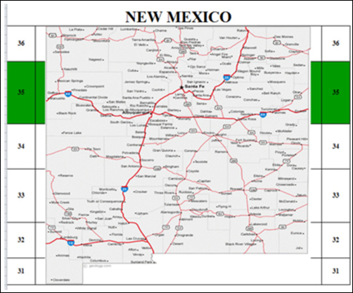
Figure 4. Example of a state map with latitude 35° selected.

Figure 5. PV panel tilt angle.
Step 2. Determine How Much Power Is Needed Each Day for the Load
Navigate to the next sheet titled Lights (Figure 6). This sheet will calculate the amount of energy needed each day based upon your power usage and type and number of loads; in this case, the system load is the light(s).
The Lights sheet shows common power requirement for different types of lights in the bottom left of this sheet (Figure 7). These values, and your entries, are used to obtain the total energy required. In addition, the average luminosity for each type of light is shown in the column "Lumens." This table can be used to compare energy requirements under different choices.
Under the heading "Quantity" (Figure 6), input the number of each size of light (40 W, 100 W, etc.) you will use. If you do not have a particular light, just leave that cell blank or enter 0.
Next, under the column "Lights," use the drop-down menu to enter the type of light (incandescent, LED, fluorescent, or halogen). The total power1 used for each type of light will be shown in the orange "Total Power (W)" cells; LED lights have the lowest power requirement and incandescent lights have the highest power requirement2 for a particular brightness. Finally, under the heading "Hours/Day," enter the total number of hours per day that you will be using each light. The amount of energy used for each light each day is calculated by multiplying the number of each type of light (e.g., 5 LED lights) by the amount of power that light requires (e.g., LED requires 30 W compared to an incandescent bulb that requires 150 W for the same amount of useful light) by the number of hours that light will be on each day. If you expect to run the light all night, use worst-case values for a night in the winter months of December and January.
If you are using a light whose wattage does not correspond to the listed examples in the "Typical power requirements for lights" table (Figure 7), or the wattage of a light is significantly different than the given values, you can input the quantity, wattage, and hours of use of this particular light at the bottom of the "Power Requirements" table (Figure 6) in the "Other Lights" cells.
The system will calculate a total daily energy requirement for each light type and then sum all these to get a "Daily Energy Requirement," which is displayed in the yellow cell. You may also enter an integer percentage multiplier (0—20%) that will add an additional percentage to this value, which can be used to adjust for an anticipated growth in the power requirements or to provide for any additional uses or quicker battery re-charge times. The new adjusted total including this additional percentage is shown in the second yellow cell with standard energy units of watt-hours/day.
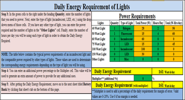
Figure 6. Lights sheet.

Figure 7. Typical power requirements of different types of lights.
Step 3. Determine the Number and Size of the Batteries Required for the System
Now that the daily energy requirement for the system load and the sunlight available at the location are known, we need to determine some additional requirements in order to calculate the size and number of batteries needed. The batteries will power the lights at night or when available sunlight is not sufficient to power the lights. So, navigate to the next sheet titled Battery Bank to start determining these values (Figure 8).
First, it is necessary to enter some values in the "SYSTEM FEATURES" area, such as system voltage, system de-rating factor, minimum temperature expected at the system location, and the PV panel efficiency. The system voltage is the voltage that you want to power your lights, usually 12 or 24 V; it is not the battery voltage, which is set later. Lights are sized to this voltage—12-V lights, 24-V lights, etc. The system de-rating value considers losses common in all electrical systems and is between 0—30%, but commonly around 5%3; higher system voltage means fewer losses in the system but some potentially higher costs in some components.
Cold temperatures affect the efficiency of the batteries. The "Minimum Temperature" cell allows you to input the expected minimum temperature where the batteries are located to take these losses into account and determine some later battery specifications. It is another "worst-case scenario" value.
Finally, the solar panel efficiency percentage takes into account losses in the PV panels due to heating, soiling, and aging of the solar panels; typical values for modern PV are about 80—95% of their rated values.
At the bottom of this "SYSTEM FEATURES" table, a new adjusted total energy requirement and the amp-hours/day required are shown in yellow. Amp-hours are the total current that we need to supply to the system each day to run the lights and recharge the batteries.
Next, enter the battery bank specifications in the "BATTERY BANK SIZE" table. The needed values are battery voltage (6 or 12 V are the most common battery voltages), battery amp-hour rating, and the maximum depth of discharge (DOD). DOD is how deeply we want to discharge the batteries to run the lights each day. The less we discharge a battery each day, the longer the total lifespan of the batteries. Typically, a good value is between 10—60% DOD, meaning 10—60% of the full battery energy is used each day.
The days of energy storage needed ("Storage Days") is how many days we want the lights to be able to operate without recharging the batteries (i.e., how many cloudy days in a row we might have at this location). The days of storage and the maximum DOD values are used to set the total capacity size and number of batteries necessary to supply power during these days without receiving energy from the panels. The "Battery Voltage" (typically 6 or 12 V) determines how many batteries of this size will be connected in series to satisfy the selected "System Voltage" (i.e., 6, 12, 24, 48 V—the load or light voltage). The battery amp-hour capacity value determines how many batteries are needed to supply the total amount of current required by the system over time. At the bottom of this table, the number of batteries connected in series and parallel is shown as well as the total number of batteries needed in the array.
A simple wiring diagram is shown in the right part of the sheet. Use this diagram as guide to enter the distances between the main components in the table above it. These distances are used to calculate the total length of the wire, which is used with system voltage to calculate the wire losses of the system. The distances are one-way and their units are feet.
In this example, we can see that now the total wattage required is 609 W each day (originally it was 161 W/day). This value takes into consideration the system de-rating, panel efficiency, and minimum temperature inputs in the "SYSTEM FEATURES" table as well as the energy requirement from the Lights sheet (161 W/day). This is the new total wattage that needs to be supplied by the PV panels to the system each day to meet the energy requirements. The next table, "BATTERY BANK SIZE," indicates that the batteries are 12 V, have 100 A/h capacity each, and have a 50% DOD. These values are used to generate the total amount of batteries required to satisfy the energy storage requirements. With these inputs, the system will need three batteries connected in parallel and will have a total maximum storage capacity of 3,600 W/day. Finally, the spreadsheet shows the actual number of days that the system will be able to run without receiving energy from the panels; in this example the system will run 2.96 days if the batteries are fully charged.
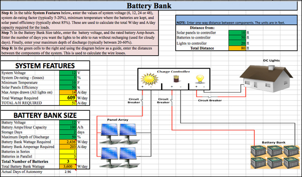
Figure 8. Battery Bank sheet.
Step 4. Determine What Size and Number of PV Panels Are Needed
Navigate to the sheet titled Array Sizing (Figure 9), whose function is to determine the number and size of PV panels required to satisfy your daily energy requirements. Panels may be combined in series (called a string) to provide enough voltage to match the system voltage, and strings can be combined in parallel to provide enough total power in watts.
In this "teaching example," you are given a choice of ten standard-sized PV panels as possible choices of panel sizes, from 50 W to 315 W each. You may choose any of the ten choices, and the system will use this choice to determine how many are needed in a string (increasing voltage) and how many strings are needed in parallel to meet total power. Given the power requirements, the system will try to optimize a recommended choice of panel size and display this recommended value for you.
In this example, the system has shown panel option 2 as the recommended option. This option needs a total of four panels connected in parallel to generate the power required by the system. Below the yellow "Total Peak Power" cell, three calculated values are highlighted in orange. The total wire length is the total distance between components entered in the previous sheet, plus an additional 15% used to account for wire losses. The next value is the minimum amperage value the controller is required to handle, which is the amount of current generated by the solar panels. This value is calculated using the rated current value in the chosen solar panel. The final value (minimum fuse size) is the total panel current plus an additional 25%, which yields the minimum size of the fuses required to protect the components from being damaged if an overload occurs. At the bottom right of the sheet, the voltage wire losses entry is displayed. This entry allows the system to determine a recommended wire size option that meets the acceptable voltage losses and can handle the total current generated for the solar panels. At the bottom of this sheet, the total power that would be generated each day with the selected panel is determined.
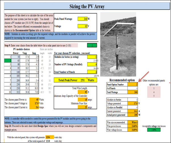
Figure 9. Array Sizing sheet.
Balance-of-System (BOS) Components
The system is composed of PV panels to capture the sun's energy, batteries to store that energy and supply it to the load at night, and the load (i.e., lights). In addition to these major components, there are several other BOS components that are required and must be selected carefully depending on system specifications. These include wire, fuses, circuit breakers, grounding, switches or disconnects, and a charge controller. The spreadsheet will recommend wire, fused breakers, and controller sizes depending on system specifications. Too small a wire will lose power and be a potential safety hazard, while too large a wire will increase costs. The requirements to protect PV systems from overcurrent conditions are defined in Article 690.9(A) of the National Electric Code. Fuses are required to protect batteries, controllers, and PV panels from line—line, line—ground, and mismatch faults.
A charge controller is an electronic device that connects the PV to the batteries. Its major function is to "control" the charging of the batteries so they do not over-charge and become damaged. A secondary function of some controllers is to control the discharge of the batteries. At a certain point of discharge, some controllers will disconnect the load (lights) so the batteries will not continue to discharge and become damaged. Batteries can be damaged by over- or under-charging. Controllers have diodes (one-way electrical valves) to stop the batteries from discharging through the PV panels at night or on very dark, cloudy days. A controller needs to be sized to the system voltage (e.g., 12 V or 24 V) and amount of current necessary. Finally, some controllers have additional features that will turn on the lights at dark and keep them on for a set time period. Some will have displays to show PV current into the battery, PV voltage, and/or current output to the load from the batteries, which can provide feedback on system efficiency.
Step 5. Summary and Economics
Navigate to the sheet titled Design Spec (Figure 10), which summarizes the design decisions and generates specifications for the designed stand-alone solar lighting system. This sheet includes many of the required materials, descriptions of each (e.g., size and model names, quantity of each item or material), an itemized cost for each item or material, and an approximate grand total price for the entire system (minus labor, construction materials, and other BOS costs). The wire is priced at a 250-ft roll, with length calculated from the total distance between components plus 25%. Federal tax credits and an average regional state tax credit are also shown; a link to specific state credits (http://www.dsireusa.org/) is provided so you can view your state's available tax credits. Example prices and tax information are from 2012 and from a random supplier. No endorsement of this supplier is implied, and prices always change and should only be used as a guide. You do not have to input any data within this sheet.
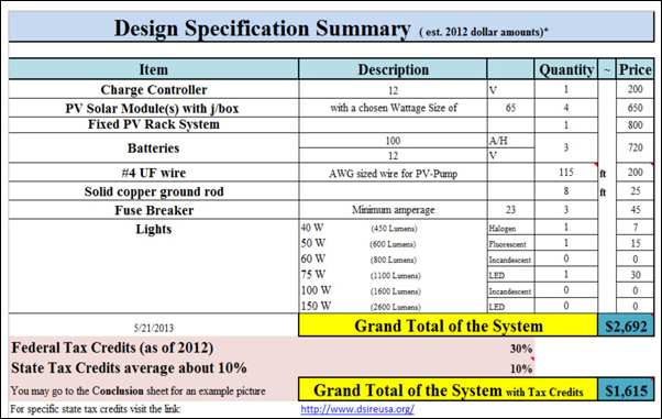
Figure 10. Design Spec sheet.
We're Done
If you want, print out the Design Spec sheet and go to the Conclusion sheet before closing the spreadsheet. The conclusion sheet shows an "example only" system picture. You have now gone through the basic step-by-step method to design a stand-alone solar lighting system. The parts and materials can be purchased from many different suppliers, many of which also provide professional installation and consulting. Remember that this is an educational tool and should only be used in that manner. If you need further assistance, you can contact local solar installers, the NMSU College of Engineering's Engineering NM program, or your local county Extension agent.
Acknowledgments
The authors wish to express extreme gratitude for the assistance of the NMSU College of Engineering and Engineering NM (http://engr.nmsu.edu/index.shtml), NMSU Cooperative Extension Service (https://extension.nmsu.edu), New Mexico Space Grant Consortium (https://www.nmspacegrant.com), Southwest Technology Development Institute (https://ece.nmsu.edu/research/swtdi/), and NMSU Department of Engineering Technology and Surveying Engineering (https://et.nmsu.edu).
Footnotes
1 Calculations of power and energy will take into account the type of light as well as its brightness (lumens). (Back to top)
2 Most of the energy used by incandescent and halogen lights is lost to heat, with less energy used to generate the light. (Back to top)
3 Energy is lost due to resistances as well as component and wire inefficiencies. (Back to top)
References
Masters, G.M. 2004. Renewable and efficient electric power systems. Hoboken, NJ: John Wiley & Sons, Inc.
National Renewable Energy Labs. 1997. Electricity when and where you need it: From the sun: Photovoltaics for farms and ranches [Online; NREL/BR-412-21732]. Available from https://www.nrel.gov/docs/gen/fy97/21732.pdf
Wiles, J. 2001. Photovoltaic power systems and the National Electrical Code: Suggested practices. Sandia National Laboratories, SAND87-0804
Internet Links
NMSU YouTube Videos on Renewable Energy Topics: https://www.youtube.com/playlist?list=PL89870B418A514D27

Thomas Jenkins has been a professor in NMSU's Department of Engineering Technology and Survey Engineering since 1990. He previously worked for many years in both private and public sectors as a computer scientist and engineer. Professor Jenkins lead the effort to develop the College of Engineering Renewable Energy Technology minor and helped establish the NMSU student organization Engineers Without Borders.
Disclaimer: This document is intended for educational purposes only, i.e., to provide a basic understanding of terminology and concepts of design. It is not intended to be used beyond this purpose. The author tried to use good engineering analysis; however, all situations are different, and you should consult a professional in all cases.
To find more resources for your business, home, or family, visit the College of Agricultural, Consumer and Environmental Sciences on the World Wide Web at pubs.nmsu.edu
Contents of publications may be freely reproduced for educational purposes. All other rights reserved. For permission to use publications for other purposes, contact pubs@nmsu.edu or the authors listed on the publication.
New Mexico State University is an equal opportunity/affirmative action employer and educator. NMSU and the U.S. Department of Agriculture cooperating.
September 2014


