CR 667
Adrian Hanson, Leeann DeMouche, Bruce Lesikar and Angela Dreager
College of Agricultural, Consumer and Environmental Sciences, New Mexico State University
Authors: Respectively, Professor and Interim Department Head, Department of Civil Engineering, New Mexico State University; Water Resource Specialist, Department of Extension Plant Sciences, New Mexico State University; Professor and Extension Specialist, Department of Biological and Agricultural Engineering, Texas AgriLife Extension Service; and Undergraduate Student, Department of Civil Engineering, New Mexico State University. (Print Friendly PDF).
Table of Contents
Introduction
Chapter 1: Historical Perspective of Native American Wastewater Management
Chapter 2: Soils and Site Inspection
Chapter 3: Septic Systems
Chapter 4: Passive Advanced Treatment Systems
Chapter 5: Mechanical Systems
Chapter 6: Disinfection
Chapter 7: Reuse and Conservation of Wastewater
Acknowledgments
References
Disclaimers
“Water is the life-giving source that sustains our crops, fish, and wildlife, from which we drink, bathe, and worship in ceremony.”
—Chehalis Tribe, Washington State
Introduction
The 2000 census data indicated that Native Americans were the fastest growing population group in the United States, and there are currently 4.5 million Native Americans in the U.S. Keeping this growing population healthy requires that Tribes take steps to ensure that sources of drinking water are clean and adequately protected against contamination, and that wastewater is appropriately managed.
With many other issues competing for the attention of Tribal leaders and members, why should wastewater receive high priority? Here are a few of the benefits:
- Protection—Protect the health and welfare of Tribal members against water-borne diseases and other contaminants.
- Society—Protect the cultural and ceremonial importance water has for many Tribes.
- Financial or Economies of Scale—Cleaning up contamination after it has occurred is more costly than protecting high-quality water resources.
- Environmental—Proper wastewater institutions and management can be integrated with—and strengthen—existing Tribal environmental activities.
Decentralized Systems
Even though the majority of wastewater generated on Tribal lands is managed through centralized wastewater treatment utilities, it is still critical to manage decentralized systems. Decentralized wastewater systems will always be present because there are areas where it is not practical or economical to connect to a centralized treatment utility. As centralized sewer management improves, decentralized portions of systems become a larger percentage of the overall risk and must also be managed.
The term decentralized refers to treating wastewater as close to where it is generated as practical. An example of this concept is the familiar septic tank/soil absorption system installed on individual lots. The decentralized concept goes beyond merely acknowledging the existence of individual user systems and instead “fills in the gap,” managing all of the systems between on-lot systems and the large-pipe conventional centralized systems. The management concepts presented in this publication are meant to assist New Mexico’s Tribes in developing responsible management alternatives that are more economically reasonable, socially responsible, and environmentally friendly than current practices.
It is important to understand that the entire wastewater treatment system, no matter how the hardware is arranged, should be managed by a trained staff. Conventional sewer lift stations and treatment plants would not perform their intended functions for very long if operations and maintenance were left solely to the discretion of individual users. The same is true for many small-scale wastewater treatment technologies. This manual and training program were developed to give Tribes both an overview of decentralized wastewater systems and a basic understanding of the operation and maintenance of these systems.
Many Tribes have already taken steps to manage and respond to growth in decentralized wastewater. For those Tribes that have some experience with decentralized wastewater systems, we recommend, if possible, that you attend training sessions with the Consortium of Institutes for Decentralized Wastewater Treatment (CIDWT). The CIDWT’s training materials for the dedicated Operations and Training Course are a valuable resource for assisting Tribes with operation and maintenance. This CIDWT course focuses specifically on assessment tools and is highly recommended as a second course to follow up on the introduction provided by this publication. For further information on CIDWT, please visit their website at https://www.onsiteconsortium.org.
CIDWT also maintains a glossary of terms related to decentralized wastewater treatment. This glossary is useful for readers who may be unfamiliar with some of the terms presented in this publication. The glossary is available at https://www.onsiteconsortium.org/glossary.html.
Chapter 1: Historical Perspective of Native American Wastewater Management
The purpose of this chapter is to give an overview of information, laws, and government agencies and a historical perspective of the progress made in environmental management on Tribal lands. Each section was written as an aid and a reminder of the great changes made to improve quality of life for Native Americans and the rest of the United States through technological advances and development of regulations.
Environment and Disease
A 1936 survey conducted by the Public Health Service (PHS) found that Indian physical surroundings must be improved if diseases associated with environmental damage were to be controlled. A later study, “Relationship of Environmental Factors to the Occurrence of Enteric Disease in Areas of Eastern Kentucky,” was completed in the 1950s, and provided data to support the premise that the incidence of acute infectious diarrheal disease could be reduced drastically by selectively modifying specific environmental factors. The study compared the incidence of enteric diseases in populations in areas that differed from one another in one or more measurable environmental sanitation characteristics (e.g., Do the toilets flush? Does plumbing provide hot and/or cold water?). These factors were selected because several diseases are readily transmitted by contaminated water supplies, including infectious hepatitis, typhoid, cholera, paratyphoid fevers, and dysenteries.
In 1955, the age-adjusted gastrointestinal disease death rate for American Indians and Alaska Natives in reservation states was 15.4 per 100,000 people. This rate was 4.3 times higher than that for all other races in the United States. It was clear from the data that water and wastewater infrastructure serving Native American populations was substandard and posed a significant threat. Between 1955 and 1985, significant strides were made toward providing potable water distribution systems and centralized wastewater treatment. With these improvements, the age-adjusted gastrointestinal disease death rate dropped to 2.2 per 100,000 people, an 86% decrease over a 30-year period.
It is clear that the contributions of environmental professionals had—and continue to have—a dramatic impact on public health and environmental quality on Tribal lands. It is important that Tribal environmental specialists realize the critical role they play in ensuring public health and the safety of the citizens on Tribal lands.
The following represents a timeline of milestone events that have been important in the development of Tribal infrastructure. Figure 1-1 demonstrates a distinct decrease in mortality rate with the increase in sanitation.

Figure 1-1. Gastroenteric and postneonatal mortality rates.
Timeline of Tribal Implementation of Wastewater Treatment In the U.S.
1910: Bureau of Indian Affairs (BIA) began a campaign to inform citizens on Tribal lands that disease could be prevented by improving the quality of personal hygiene, waste disposal, and diets.
1912: Congress approved a study conducted by the PHS to allow medical officers to study the prevalence of disease among Native Americans. The study found that sanitation on Tribal lands was unsatisfactory and that actions should be taken to improve the quality of sanitation.
1927: PHS sanitary engineers began helping BIA staff survey water and sewer systems and investigate other basic sanitation problems. The efforts of PHS were mainly focused on schools, hospitals, and agency compounds.
1952: Twelve Native Americans were hired and trained for the position of sanitarian aide. Three were the first designated Tribal environmental specialists. This was the beginning of the concept of Tribal citizens gaining the expertise to develop and inform the public of the sanitation needs of Tribes and Nations.
1959: The Indian Sanitation Facilities Act (P.L. 86–121) was passed and enabled legislation for the Indian Sanitation Facilities Construction Program (ISFCP). The Act appropriated $600 million to provide sanitation facilities for American Indians and Alaska Natives between 1960 and 1989. With the beginning of the ISFCP came the start of a construction program that provided adequate drinking water systems and sewage and solid waste disposal systems for Indian homes and communities.
1988: Indian Health Care Amendments were passed and were the premise for continual improvement of sanitation and elimination of deficiencies in homes and communities of American Indians and Alaska Natives.
History of Tribal Implementation of Wastewater Treatment: New Mexico Tribal Lands
Regardless of the progress made in establishing centralized treatment centers in urban clusters, there will always be areas where centralized systems are not practical. These will be served now and in the future by well-designed, environmentally safe onsite wastewater treatment systems. The environmental professional is critical for ensuring that these systems continue to operate effectively once installed.
The Indian Health Service (IHS) has historically provided sanitation facilities for homes on Tribal lands under Public Law 86–121, which was signed by President Eisenhower on July 31, 1959. The passage of this Act was a milestone in Indian health legislation and lead to the creation of a Sanitation Facilities Construction (SFC) Program within IHS. During the 1950s, IHS began constructing sanitary pit privies for scattered homes to help establish better sanitation and well-being. At Laguna Pueblo, the privies were located in the cliff areas of the village, but because of their great distance from homes, the privies were only used during daylight hours. Homes at Isleta Pueblo had pit privies and cesspools. While this was the beginning of good sanitation, the pit privies and cesspools failed to meet good sanitary disposal requirements.
In the early 1960s, design and construction of small community wastewater disposal systems consisting of unlined sewage lagoons and sewer collection systems were completed in some of the pueblo villages and small scattered communities on the Mescalero Apache Reservation. The sewer pipe was made out of clay and the manholes were constructed using concrete blocks.
In 1968, the Mescalero Tribal Housing Improvement Program and IHS embarked on a joint project to satisfy sanitation needs. Under this project the Mescalero Apache Tribe, individual homeowners, and various government agencies combined resources to convert common house facilities into substantially better sanitation facilities. During this time, Tribal members received basic training in the building trades, which facilitated installation of home sanitation fixtures. Individual homeowners purchased items such as bathtubs, lavatories, and hot water heaters, and IHS provided kitchen sinks and water closets.
Homes not near a community wastewater disposal system were provided with a septic tank and gravel drainfield system. Clay pipe was originally used in the drainfields, but as time passed, the systems were updated to follow industry trends in the types of materials used for drainfields. In the late 1980s, plastic infiltrators were utilized in the drainfield system, eliminating the need for gravel and reducing the land requirement for such a system. From the late 1990s to the present, technological advances in the field of onsite wastewater treatment have been tremendous. The new types of systems available, pressurized mounds, peat filter systems, and Eljen In-Drains, along with many others, have been installed on Tribal lands.
All small- to medium-scale distributed wastewater treatment systems require regular maintenance to ensure a long life and satisfactory performance. As the sophistication of the systems increases, the need for management of operations and maintenance also increases.
<| Note: Most of the information in this section comes from a recent report that commemorates the 50th anniversary of the passage of Public Law 86-121 and the many public health achievements in Tribal communities that may be attributed to the work of the Sanitation Facilities Construction Program. Public Law 86-121 is the Indian Sanitation Facilities Act and has been one of the most effective pieces of legislation impacting Indian health in IHS history. |
Management of Onsite Wastewater Treatment
Through Tribal initiative and assistance from IHS, Tribal entities across the United States have moved toward a wastewater treatment model focused on centralized treatment. The strategy has been to collect wastewater from each buildup area, transport it to a centralized location, and treat the wastewater to the level appropriate for discharge to the environment. This has been a very successful approach to controlling disease and providing a continually improving level of public health. It also provides a solid management structure for infrastructure oversight.
However, there are always homes and businesses that, due to their remote locations or economic barriers, are not easily served by a centralized system. It is important to have a strategy for managing these decentralized systems. Decentralized systems will be a reality on Tribal lands for the foreseeable future, so a proactive management stance is strongly recommended. The utility management structure currently in place provides an opportunity for rational management of these decentralized systems.
Many of the government entities responsible for managing these decentralized systems, both Tribal and non-Tribal, manage them by ignoring them. Because the traditional septic tank/drainfield is a robust, reliable treatment technology, it is actually successful much of the time. Unfortunately, when it is not successful, the result can be illness and damage to the environment. The U.S. Environmental Protection Agency (EPA) has developed a number of management strategies (models) for government agencies responsible for managing decentralized wastewater treatment facilities within their jurisdictions. These are valuable tools to assist Tribes and Pueblos with responsible oversight of decentralized systems. Table 1-1 summarizes three models and illustrates scenarios that may be of interest to Tribal governments.
Table 1-1. Management Models of Onsite and Decentralized Wastewater Systems.
| Model/ Resource Development |
Application | Description of Program | Benefits | Limitations |
| Homeowner Awareness |
Areas of low environmental sensitivity for conventional onsite systems. |
Systems properly sited and constructed based on prescribed criteria. | Ease of implementation; based on existing prescriptive system design and site criteria. Provides an inventory of systems that is useful in system tracking and area-wide planning. |
No compliance/problem identification mechanism. Sites must meet siting requirements. Cost to maintain database and owner education program. |
| O&M | Areas of low to moderate sensitivity, small cluster systems, and systems treating high-strength waste. | Systems properly sited and constructed. More complicated treatment systems, including mechanical components, or small clusters of homes. Service contracts are required. Service contract for tracking systems. Minimum for large capacity systems. |
Reduces the risk of treatment system malfunctions. Protects homeowner’s investment. Allows systems in more environmentally sensitive areas. Operating permit requires regular compliance monitoring reports. Identifies non-compliant systems and initiates corrective actions. Decreases need for regulation of large systems. |
Difficulty in tracking and enforcing compliance because it must rely on the owner or contractor to report a lapse in a valid contract for services. No mechanism provided to assess the effectiveness of the maintenance program. Higher level of expertise and resources for regulatory authority to implement. Requires permit tracking system. Regulatory authority needs enforcement powers |
| Resource Management |
Areas of moderate to high sensitivity, cluster systems; preferred management program for cluster systems for multiple users. |
Establishing system performance and monitoring requirements. Professional O&M through RME. Service contract for tracking systems. Trained and licensed operators. Professional management of decentralized treatment system. |
O&M responsibility transferred from the system owner to a professional RME hat is the holder of the operating permit. Identifies problems needing attention before failures occur. High level of oversight if system performance problems occur. Simulates model of central sewerage, reducing the risk of non-compliance. Allows use of onsite treatment in more environmentally sensitive areas. Allows effective area-wide planning/watershed management. Removes potential conflicts between the user and RME. |
Enabling legislation may be necessary to allow RME to hold the operating permit for an individual system owner. RME must have owner approval for repairs; there may be conflict if performance problems are identified and not corrected. Need for easement/right of entry. Need for oversight of RME by the regulatory authority. Enabling legislation and/or formation of special district may be required. May require greater financial investment by RME for installation and/or purchase of existing systems or components. Private RMEs may limit competition. Homeowner associations may not have adequate authority. |
| Source: EPA, 2005 | ||||
It must be stressed that these are suggested models, and local preferences and regulations may make a hybrid model a better fit for a specific situation. It is up to each government to craft the management strategy that best meets local needs. The EPA models are presented as a point at which to start discussion; they represent the EPA’s perspective and cover the intended applications, actions involved, and responsibilities required for appropriate management of decentralized systems.
In EPA’s suggested minimum management model (“Homeowner Awareness” in Table 1-1), the responsible jurisdiction (Tribe) should educate the homeowner and remind the homeowner of periodic maintenance activities. Under this model, the jurisdiction keeps a database documenting the location of all distributed wastewater systems, educates homeowners, and sends out periodic reminders to have tanks pumped. The government agency is not responsible for any activity other than friendly reminders.
In the second model, “O&M,” the government agency issues an operating permit to the homeowner and the homeowner is held accountable by the regulatory arm of the government agency. This model relies on the homeowner to operate and maintain the system, but a permit is available as a tool to encourage accountability.
In the third model, “Resource Management,” the management of the onsite systems is turned over to a Responsible Management Entity (RME). The homeowner must have a contract with the RME, and the RME is accountable to the government regulatory arm. In a hybrid of this model, the RME is an arm of the government (Tribe).
The EPA describes five management levels or models in the Handbook for Managing Onsite and Clustered (Decentralized) Wastewater Treatment Systems (2005). Table 1-1 is a summary of Models 1, 3, and 4.
Regulations
The onsite wastewater regulations are all developed at a local or state level. It is the right of each Tribal government to develop its own onsite (liquid waste) regulations. If a Tribal government wants to formalize its liquid waste treatment regulations, the logical place to start is with guidance from the closest local jurisdictions (New Mexico Environment Department), the EPA, and the IHS. A few of the important agencies that are specifically poised to provide guidance and assistance to Native American government agencies are listed below, with a brief description of each.
Indian Health Service: IHS provides healthcare to the Native American community that is culturally acceptable and available.
New Mexico Environment Department (NMED): NMED is the state-level counterpart to EPA and has State-Level Primacy for a number of federal regulations on non-Tribal lands. NMED has jurisdiction over all non-Tribal liquid waste systems in New Mexico, with the exception of Bernalillo County. NMED has a Tribal liaison charged with assisting the Tribes.
U.S. Environmental Protection Agency: EPA serves to protect the health of the public as well as the environment. All Class V wells on Tribal lands, which include some of the larger septic systems and industrial septic systems, are regulated by the EPA through EPA’s
Region 6 office.
Federal Emergency Management Agency (FEMA): FEMA is responsible for the security of the public by reducing loss of life and property as a result of, and protecting the nation from, disaster.
Occupational Safety and Health Administration (OSHA): OSHA ensures the safety and health of America’s workers by setting and enforcing workplace safety standards. Issues associated with trenching and confined entry are under their jurisdiction.
Federal Regulations
If a state or Tribe demonstrates to EPA’s satisfaction that the government entity is capable of managing federally-mandated programs, the state or Tribal regulatory agency will be granted primacy, and local management of the regulatory program will be turned over to the state or Tribe, with EPA oversight.
What is primacy? Primacy is the earned right of a government agency to take full responsibility for the interpretation, management, and enforcement of a federal law at a local level. The State of New Mexico has primacy on non-Tribal lands for a number of environmental regulations. Tribal governments have the right to establish their own environmental agencies and seek primacy for environmental regulations within their own jurisdictions.
Clean Water Act (1977)
The legislation of most importance to the management of onsite wastewater discharging to surface water is the Clean Water Act (CWA). This legislation was initially intended to return the surface waters of the U.S. to a pristine state. It is now the primary vehicle for managing wastewater treatment and discharge to the environment in the U.S.
The CWA states that publicly owned treatment works discharging to a surface water of the U.S. must meet either effluent limitations based upon secondary treatment or any more stringent limitations. These limitations include those necessary to meet water quality standards, treatment standards, or schedule of compliance. They may be established pursuant to any state law or regulation or any other federal law or regulation, or required to implement any applicable water quality standard established pursuant to this Act.
Underground Injection Control (UIC) Program under the Clean Water Act
Even though most septic tanks do not discharge into surface water, the water treated by septic systems must meet secondary treatment standards as defined in the CWA. In very small applications, the septic tank is the primary treatment portion of the system, while the biomaterial at the soil interface in the drainfield provides the secondary treatment. As the system increases in size—and thus loading on the environment—advanced treatment techniques must be applied so that wastewater quality meets secondary treatment standards prior to being discharged into the drainfield. Under most jurisdictions, this approach is followed until the wastewater flow exceeds 5,000 gallons per day (gpd), and at this hydraulic loading the system shifts to the Class V Injection Well regulations. The effluent from these medium-sized systems must be treated to the standards of the Underground Injection Control (UIC) Program regulations, and these systems require permitting. Some jurisdictions reduce the size of systems at which Class V injection well regulations must be met. In New Mexico, any flow in excess of 2,000 gpd requires a Class V permit (groundwater discharge permit, GWDP).
The UIC Program requirements were developed by EPA and designed to be adopted by states, territories, and Tribes. These entities can submit an application to EPA to obtain primacy, and agencies that have been granted primacy oversee the injection activities in their jurisdictions. Currently, New Mexico has primacy over all well classes. For more information on the UIC permitting process, refer to Title 40 of the Code of Federal Regulations (CFR) Part 145.
A Class V well is a system used to inject non-hazardous fluids underground. Fluids are injected either into or above an underground source of drinking water. This diverse group of wells ranges from simple shallow wells to complex experimental injection technologies.
Most Class V wells are “low-tech” and depend on gravity to drain fluids directly below the land surface. Drywells, cesspools, and septic system drainfields are examples of simple Class V wells. Because their construction often provides little or no pretreatment and the fluids are injected directly into or above an underground source of drinking water, proper management is important.
More sophisticated Class V wells may rely on gravity or use pressure systems for fluid injection. Some sophisticated systems include advanced wastewater disposal systems used by industry, experimental wells used to test new or unproven technologies, and even systems used to inject and store water for later reuse.
Eight New Mexico Tribes have adopted CWA standards as noted in the “Federal Water Quality Standards for Indian Country: Proposed Rule.” This document, while never implemented, is a good reference and can be found on the EPA Water Science website at https://water.epa.gov/scitech/swguidance/standards/upload/2008_05_16_tribes_proposedcore2001.pdf.
Tribal environmental specialists have come far from the days when their role was to assist homeowners to install sanitary fixtures in Tribal homes. The Tribal experts of today work with complex infrastructure, complex regulations, and an ever more knowledgeable public. It is important that the Tribal environmental professionals grow with the industry. This document is intended to provide information important for managing the installation and maintenance of the small- to medium-sized distributed wastewater treatment systems.
Chapter 2: Soils and Site Inspection
This chapter will cover treatment system site inspection, site slope requirements, soil composition, and the effect of soil composition on soil’s ability to transmit water/effluent. Portions of this chapter require prior knowledge and expertise in soil science to completely understand and use the material presented.
Soil is the portion of an onsite treatment system that treats the septic tank effluent. Soil treats the effluent by removing contaminants through natural physical, chemical, and biological processes that are active in healthy soil. From a practical view, soil provides the secondary treatment in a conventional septic system. Knowledge of soil and soil processes will allow the manager/operator to place proper value and emphasis on operational issues and maintenance that protect the soil.
Many factors contribute to how a soil will behave, including chemical and physical factors. Chemical factors can generally be related to the coloring of the soil (i.e., redoximorphic characteristics), which can then be analyzed to determine the soil’s mineralogy and how the soil formed. Physical factors include air movement, storage, root growth, location, depth of soil layers, and biological activity.
In addition to the soil’s characteristics, there are land use and site issues that will be important. Land use issues include determination of easements and other setbacks and location of utilities and wells. Site characteristics include site topography, limiting features, and vegetation. Limiting features generally include zones of seasonal, perched, or long term saturation; location of hard bedrock with few connected pores or fractures; location of dense pans or cemented layers; and depth to coarse sands, gravel layers, or fractured bedrock.
Task List for Site Inspection
Upon arriving at the site, make a walking tour along property lines, noting on your site plan any items that may affect the placement of a system. Look for signs of buried utilities and easements, and confirm that buried utilities that were found during your preliminary investigation are either identified or are absent. In any jurisdictions where “one-call” is available, it is not only convenient to call the utility company, it is usually the law. Make notes (including locations) of the following observations.
- Aesthetic features such as trees or views
- Buildings (on property and adjacent properties)
- Driveways
- Easements
– Natural gas
– Overhead/underground power
– Water
– All other utilities - Existing sewer lines (on property and adjacent properties)
- Existing wastewater systems (on property and adjacent properties)
- Existing water lines (on property and adjacent properties)
- Percolation holes and/or test pits
- Photo points (if photos are taken)
- Property lines
- Proposed residence
- Road cuts
- Rock outcroppings
- Survey monuments
- Vegetation
- Water features
– Dry washes
– Live streams
– Ponds or lakes
– Swimming pools - Wells (on property and adjacent properties)
Topography describes the site’s surface contour or shape. Topography can be documented using the following four descriptive terms.
- Smooth—boundaries are flat
- Wavy—boundaries have channels or alternating contours
- Irregular—boundaries have no distinct patterns
- Broken—boundaries are disjointed
What are the tasks of the soil scientist or trained environmental specialist?
- Study local soil information from the county soil survey.
- Conduct a visual assessment of the site to identify landscape features.
- Probe the soil to delineate soil resources on the property.
- Excavate soil borings and pits to prepare profile descriptions of major soils on the property.
- Match the soil resource to appropriate treatment technology through a suitability assessment.
It is widely agreed that the most reliable way to determine soil texture and structure is to use the services of a trained soil scientist. The majority of this chapter will be spent discussing this approach. However, both the Natural Resources Conservation Service (NRCS) and U.S. Department of Agriculture (USDA) soil surveys and the percolation test, which are also used, will be discussed first.
Published Soil Surveys
USDA-NRCS soil data are used in some jurisdictions to determine suitability of soils for septic systems. USDA-NRCS has surveyed most of the state of New Mexico, and the available interactive web soils survey maps can be found on the USDA-NRCS soils website at https://websoilsurvey.nrcs.usda.gov/app/WebSoilSurvey.aspx.
Percolation (Perc) Test
Permeability is a necessary measure of a soil’s ability to transmit fluid; soils must be permeable so that effluent can move through and past soil horizons (distinct soil layers). To determine permeability, information regarding a soil’s hydraulic conductivity and saturation (water content) is required. Hydraulic conductivity is a measure of how quickly soil transmits water and is dependent on the saturation of the soil. In soils with multiple horizons, it is important to measure the hydraulic conductivity of each horizon or to assess conductivity based on soil texture. An empirical method for measuring hydraulic conductivity is the percolation test.
For years, soil permeability was assessed by simply performing a percolation test. In this test, a standardized hole is dug (roughly 18 in. deep and 4 in. across), pea gravel is placed in the bottom of the hole, and the soil surrounding the hole is soaked with water for 24 hours. At the end of the soak period, the rate at which water is absorbed by the soil (hydraulic acceptance) is measured. This test provides very erratic results in some arid climate soils. If a soil is extremely dry and contains swelling clays, it may take days for the soil to fully wet and swell shut the cracks in the soil. Any percolation test performed at a significant distance from the soil interface before these cracks swell shut will provide an inaccurate hydraulic acceptance rate for the soil. This will result in a drainfield that is too small, and will frequently result in short drainfield life expectancy (less than 10 years).
Many onsite wastewater professionals have long advocated using a soil assessment from a soil science point of view, instead of a percolation test, to size drainfields; this is by far the most widely supported means of determining hydraulic conductivity and drainfield size. In a soil assessment, permeability is generally determined based on several soil characteristics such as texture, structure, consistency, and color. This may require that each individual receive training or that a staff soil scientist be hired. If you are not a trained soil technician or soil scientist, you may need to consult a qualified professional for the task of soil classifications before you begin working on your septic system.
While it is best to have a professional conduct soil assessments and interpret the results, conducting a soil assessment is not terribly difficult, and anyone with a few hours of training and a few more hours of practice can be taught to determine texture. The following sections will provide some theoretical understanding.
Soil Horizons
In a vertical cross-section of soil, layers (or horizons) can be clearly seen. The top layer has the most organic matter and is the most biologically active. This top layer usually contains the majority of the root mass from plants growing on the soil surface. Each subsequent layer is less biologically active. If we know the soil name or the soil designation, we can take advantage of the cumulative knowledge gathered by soil scientists in the agricultural sector to understand soil as it relates to waste treatment systems. Without attempting to become soil scientists, let’s take a look at soil structure and the naming of soils, which are of primary importance in drainfield design.
Master Horizons and Layers
Small-scale wastewater treatment systems consist of treatment and dispersal, which will be discussed later in this publication. The dispersal system for treated wastewater will typically be located in one of the soil horizons listed below. Drip irrigation will be in the O or A horizon, the low-pressure pipe on the shallow end will be located anywhere between the bottom of the A horizon to the C horizon, and a conventional drainfield will usually be in the C horizon or deeper. Below is a brief discussion of the different soil horizons.
O horizon—Topmost layer, which is dominated by organic material such as leaf litter.
A horizon—This is the root zone for most grasses. It is composed of mineral particles that have been mostly or completely broken down from the original rock structure and that formed at the surface or below an O horizon. The A horizon is (i) characterized by an accumulation of humified organic matter intimately mixed with the mineral portion and not dominated by properties characteristic of E or B horizons, or (ii) has properties resulting from cultivation, pasturing, or similar kinds of disturbance.
E horizon—A mineral horizon in which the main feature is loss of silicate clay, iron, aluminum, or some combination of these, leaving a concentration of sand and silt particles of quartz or other resistant materials.
B horizon—The horizon that forms below an A, E, or O horizon; it is dominated by obliteration of much or all of the original rock structure and shows one or more of the following:
- illuvial (movement from upper to lower soil layers) concentration of silicate clay, iron, aluminum, humus, carbonates, gypsum, or silica;
- evidence of removal of carbonates;
- residual concentration of sesquioxides;
- coatings of sesquioxides that make the horizon conspicuously lower in value (color lightness/darkness), higher in chroma (color purity), or redder in hue (color) than overlying and underlying horizons without apparent illuviation of iron;
- alteration that forms silicate clay or liberates oxides or both, and that forms granular, blocky, or prismatic structure if volume changes accompany changes in moisture content; or
- brittleness.
C horizon—Horizon, excluding hard bedrock, that is little affected by pedogenic (soil forming) processes and lacks properties of O, A, E, or B horizons. The material of the C horizon may appear different than the material that formed the soil, and may have been modified even if there is no evidence of pedogenesis.
R horizon—Unweathered, hard bedrock, including granite, basalt, quartzite, and indurated limestone or sandstone, that is sufficiently coherent to make hand digging impractical.
Transitional layer—The area that transitions one horizon into the next.
The A horizon, or at least the majority of the root zone, is usually above the dispersion system (trench) of onsite treatment systems. In some soils, the A horizon can be several feet thick. In many New Mexico soils, however, the A horizon is very shallow. In eastern and midwestern states, the dispersion interface (trench bottom and sides) is usually in the lower A horizon or in the B horizon. In western states, it is common for the A and B horizons to be very shallow, and the trench may be below the entire B horizon. The C and R horizons will frequently constitute a limiting layer. It is important to identify the depth at which cemented layers (caliche or sandstone), hard rock, fractured rock, or heavy clays exist. These are not appropriate for treatment, even if they may pass liquid at an adequate rate.
Color
It takes hours of formal training and considerable practice to become fully comfortable with soil texture and color assessment. This section is intended to expose you to some of these concepts, provide a basic description of the process, and encourage you to use a soil expert to assist you. It is worth noting that the process described here is the process that environmental specialists with IHS have been using for over a decade.
Soils best suited for septic systems are usually brown, yellow, or bright red. Color is perhaps the most obvious and easily determined soil property, and important soil characteristics can be inferred from soil color. Well-drained soils have uniform, bright colors, while soils with a fluctuating water table have a mottled pattern of gray, yellow, and/or orange colors. Organic matter darkens the soil and will mask all other coloring agents; it is found mostly in surface layers. Iron (Fe) is the primary coloring agent in the subsoil. The orange-brown colors associated with well-drained soils are the result of iron oxide stains coating individual particles. Manganese (Mn) is common in some soils and produces a very dark black or purplish black color. Several other soil minerals have distinct colors, making their identification straightforward. For example, glauconite is green; quartz has various colors, but is often white or gray; feldspars range from pale buff to white; micas may be white, brownish black, or golden; and kaolinite appears gray to white.
Each person perceives color differently, and color determination can be quite subjective if just a verbal description is used. There is therefore a need to standardize color description. To do this, some basic understanding of the properties that govern color is needed. White light (or the visible spectrum) can be broken into the colors of the rainbow: red, orange, yellow, green, blue, indigo, and violet (ROYGBIV). Each of these colors corresponds to a specific wavelength in the visible spectrum. When we see colors, we are actually seeing the particular wavelengths that are reflected by the surface of what we are looking at: If we see a red object, the red wavelength is being reflected and all other colors are being absorbed by the object. It is possible to measure the wavelength reflected by an object, but the equipment is expensive and not easy to use in the field. Thus, determining colors using spectral wavelength is not ideal.
In the early 1900s, work was done to try to make color description easier, and a method was devised using the artist’s color wheel. In the color wheel, each pie wedge represents a particular spectral wavelength or hue (e.g., R = red). These wedges can be further divided into smaller sections (1R = 10% red, 10R = 100% red). Typically, only the 25, 50, 75, and 100% hue values are used (2.5, 5, 7.5, and 10). However, hue does not tell a color’s whole story; value (lightness or darkness) and chroma (purity or intensity) also describe a color. Value refers to how light or dark the color is relative to a neutral gray scale. Value extends from pure black (0/) to pure white (10/), and is a measure of the amount of light that reaches the eye; gray is perceived as halfway between black and white and has a value notation of 5/. Lighter colors have values between 5/ and 10/, while darker colors are between 5/ and 0/. Chroma is the relative purity or strength of a hue. Chroma indicates how much neutral gray is in the spectral color. Chromas extend from /0 for neutral colors to /8 as the strongest, purest expression of the color.
The Munsell Color System, developed by Albert Munsell in the early 1900s, combined the measurements of hue, value, and chroma into a system to standardize color description. It was initially designed for manufacturing, but soon made its way into any field that needed to record and communicate color. In the Munsell Color System, the color is notated as an alphanumeric term of Hue Value/Chroma, e.g., 10YR 5/6 is a 100% pure yellow-red with a value of 5/ (medium) and a chroma of /6 (high). Some colors have symbols such as N 6/. These are totally achromatic (neutral color) and have no hue and no chroma, only a value. Munsell color charts are often used by trained soil scientists to help describe colors in the field. Typically, the average homeowner or installer will not have the knowledge required to use this tool. For additional information on the Munsell color system see, https://en.wikipedia.org/wiki/Munsell_color_system.
Soil Color in the Field
When recording soil color in the field, it is important to follow established procedures to ensure consistent, usable results. Soil should be moist when recording color; although this is the most common way soil colors are recorded, they can be recorded in a dry state. Always note the moisture of the sample. Always use a freshly exposed face or ped (single unit of soil structure). Do not crush or rub the soil before recording a color unless it is an organic sample. Colors must always be determined in natural light (direct sunlight), and should not be determined late or early in the day as the sun angle can alter the observed color; colors should never be determined under artificial light. Finally, color should not be determined when one is wearing sunglasses or tinted glasses.
In describing colors, it is important to determine the variation in color throughout the soil. Matrix color is the color that occupies the greatest volume of the horizon. Some horizons have several colors, and the color that appears the most is recorded first, followed by the next most prevalent color, and so forth.
Redoximorphic features (mottles) result from the reduction, oxidation, and translocation of Fe and/or Mn; oxidation adds Fe and/or Mn to soil and gives it a red, brown, or yellow color, while reduction removes these elements to leave a gray-colored soil. Mottles are color patterns not related to soil wetness; rather, they are often related to parent material, mineralogy, or weathering patterns. Mottles may be described separately for any feature such as peds, concretions, nodules, cemented bodies, filled animal burrows, etc. Gley colors are low chroma matrix colors with or without mottles. If the soil has a gley color, the soil is likely to be reduced and wet for much of the year. The percent of the given mottle should be recorded. Although NRCS does use the Munsell color system to indicate abundance, it is better to record the actual percent using the charts in the Munsell book to estimate.
Contrast refers to how easy it is to see a mottle as compared to the matrix color. There are three classes of contrast: faint, distinct, and prominent (Table 2-1). Faint contrast is evident only on close examination. Distinct contrast is readily seen, but is moderate when compared to the matrix color. Prominent contrast is a strong contrast between the mottle color and the matrix color.
Table 2-1. Contrast Chart
| Contrast Class, Code |
Difference in Color Between Matrix and Mottle Using Munsell Book |
|||
| Hue | Value | Chroma | ||
| Faint F | Same | 0 to <2 | and | <1 |
| Distinct D | Same Same 1 page |
>2 to <4 Or <4 <2 |
and and and |
<4 >1 to <4 <1 |
| Prominent P | Same 1 page 2+ pages |
>4 >2 >0 |
or or or |
>4 >1 >0 |
Soil Texture and Particle Size Distribution
Texture or particle size is used to determine the long-term hydraulic acceptance rate (LTAR) ranges for designing onsite systems. Texture by itself only refers to the amount of sand, silt, and clay in the soil. The practitioner infers from this information what the pore size distribution is, and thus infers the rate at which water will flow through the soil. Texture by itself is not enough to determine LTAR; it simply helps to define the range of possibilities.
Particle size distribution describes the abundance of the variously sized particles that constitute the mineral portion of soil materials. The larger particles (pebbles, cobbles, stones, and boulders) are called rock fragments. The term “coarse fragments” excludes the stones and boulders classes in the rock fragments. The finer-sized fractions are called the fine-earth fraction (smaller than 2 mm diameter). The content of rock fragments is determined by estimating the proportion of the soil volume they occupy. Particle size distribution of the fine-earth fraction is determined in the field mainly by feel.
Rock Fragments
Rock fragments are unattached pieces of rock 2 mm in diameter or larger that are moderately cemented or more resistant to rupture. Rock fragments include all sizes with surface areas less than the size of a pedon (approximately 1 m2). Rock fragments are described by size, shape, and, for some, the kind of rock. The classes are gravels, cobbles, channers, flagstones, stones, and boulders (see Table 2-2). If a size or range of sizes predominates, the class is modified, as for example “fine gravels,” “cobbles 100 to 150 mm in diameter,” or “channers 25 to 50 mm long.” The terms “gravel” and “cobble” are usually restricted to rounded or subrounded fragments; however, they can be used to describe angular fragments if they are not flat. Words like chert, limestone, and shale refer to a kind of rock, not a shape of rock. The composition of the fragments can be given using a combination of type and shape of rock, for example “chert pebbles” or “limestone channers.” The largest size of gravel is 76 mm; this coincides with the upper limit used by many engineers for grain-size distribution computations. The 5-mm and 20-mm divisions for the separation of fine, medium, and coarse gravel coincide with the sizes of openings in the “number 4” screen (4.76 mm) and the “3/4-inch” screen (19.05 mm) used in engineering to separate fractions of rock fragments. The 250-mm limit is used to separate cobbles from stones, and the 600-mm limit is used to separate stones from boulders. The 150-mm (channers) and 380-mm (flagstones) limits for thin, flat fragments follow conventions used for many years to provide class limits for plate-shaped and crudely spherical rock fragments that have about the same soil use implications as the 250-mm limit for spherical shapes.
Table 2-2. Terms for Describing Rock Fragments
| Size (mm) | Type | Abbreviation | Descriptive Term |
| Rounded, subrounded, and irregular | |||
| 2–76 | Gravels | gr | gravelly |
| 2–5 | Gravels | grf | fine gravelly |
| 5–20 | Gravels | grm | med. gravelly |
| 20–76 | Gravels | grc | coarse gravelly |
| 76–250 | Cobbles | cb | cobbly |
| 250–600 | Stones | st | stony |
| >600 | Boulders | by | bouldery |
| Flat (long) | |||
| 2–150 | Channers | cn | channery |
| 150–380 | Flagstones | fl | flaggy |
| 380–600 | Stones | st | stony |
| >600 | Boulders | by | bouldery |
Fine-Earth Fraction
Table 2-3 shows the various size divisions that make up the fine-earth fraction of soil materials.
Table 2-3. USDA Size Categories for the Fine-Earth Fraction (Mineral Soil Materials <2 mm)
| Class | Abbreviations | Size (mm) |
| Very coarse sand | VCOS | 2.0–1.0 |
| Coarse sand | COS | 1.0–0.5 |
| Medium sand | MS | 0.5–0.25 |
| Fine sand | FS | 0.25–0.10 |
| Very fine sand | VFS | 0.10–0.05 |
| Silt | SI | 0.05–0.002 |
| Clay | C | <0.002 |
Soil Texture
Soil texture refers to the proportion of different fine-earth particles (i.e., smaller than 2 mm) present in the soil as determined from a laboratory particle size distribution analysis. Field estimates should be checked against laboratory determinations, and the field criteria should be adjusted as necessary. Soil texture is used to describe as much as possible about a soil in as few words as possible. When you know the texture of a given soil, you can approximate or estimate many other soil properties, such as bearing value, water-holding capacity, tendency to frost heave, and adaptability to soil-cement construction.
Soil Texture Classes Defined
The texture classes are sand, loamy sand, sandy loam, loam, silt loam, silt, sandy clay loam, clay loam, silty clay loam, sandy clay, silty clay, and clay. Sands are subdivided into coarse sand, sand, fine sand, and very fine sand. Subclasses of loamy sands and sandy loams that are based on sand size and are named similarly (see Table 2-3 for abbreviations).
Sand: 85–100% sand-sized particles, 0–15% clay, and 0–10% silt.
Coarse sand: 25% or more very coarse and coarse sand and less than 50% any other single grade of sand.
Sand: 25% or more very coarse, coarse, and medium sand (but less than 25% very coarse plus coarse sand) and less than 50% either fine or very fine sand.
Fine sand: 50% or more fine sand; or, less than 25% very coarse, coarse, and medium sand, and less than 50% very fine sand.
Very fine sand: 50% or more very fine sand.
Loamy sand: 70–91% sand-sized particles, 0–15% clay, and 0–30% silt.
Loamy coarse sand: sand portion contains 25% or more very coarse and coarse sand and less than 50% any other single grade of sand.
Loamy sand: sand portion contains 25% or more very coarse, coarse, and medium sand (but a total of less than 25% both very coarse and coarse sand) and less than 50% either fine sand or very fine sand.
Loamy fine sand: sand portion contains 50% or more fine sand; or, less than 50% very fine sand and a total of less than 25% very coarse, coarse, and medium sand.
Loamy very fine sand: sand portion contains 50% or more very fine sand.
Sandy loam: 7–20% clay, more than 52% sand-sized particles, and 0–30% silt plus clay in a 1:2 silt:clay ratio; or, less than 7% clay, less than 50% silt, and more than 43% sand-sized particles.
Coarse sandy loam: total of 25% or more very coarse and coarse sand and less than 50% any other single grade of sand.
Sandy loam: total of 30% or more very coarse, coarse, and medium sand, but a total of less than 25% very coarse and coarse sand and less than 30% fine and very fine sand; or, a total of 15% or less very coarse, coarse, and medium sand, less than 30% fine sand, and less than 30% very fine sand, with a total of 40% or less fine and very fine sand.
Fine sandy loam: 30% or more fine sand and less than 30% very fine sand; or, a total of 15–30% very coarse, coarse, and medium sand; or, a total of more than 40% fine and very fine sand, at least half of which is fine sand, and a total of 15% or less very coarse, coarse, and medium sand.
Very fine sandy loam: 30% or more very fine sand and a total of less than 15% very coarse, coarse, and medium sand; or, more than 40% fine and very fine sand, at least half of which is very fine sand, and a total of less than 15% very coarse, coarse, and medium sand.
Loam: 7–27% clay, 28–50% silt, and 52% or less sand.
Silt loam: 50% or more silt and 12–27% clay; or, 50–80% silt and less than 12% clay.
Silt: 80% or more silt and less than 12% clay.
Sandy clay loam: 20–35% clay, less than 28% silt, and more than 45% sand.
Clay loam: 27–40% clay and 20–46% sand.
Silty clay loam: 27–40% clay and 20% or less sand.
Sandy clay: 35% or more clay and 45% or more sand.
Silty clay: 40% or more clay and 40% or more silt.
Clay: 40% or more clay, 45% or less sand, and less than 40% silt.
A texture triangle (Figure 2-1) is used to resolve problems related to word definitions of the textures, which are obviously somewhat complicated.
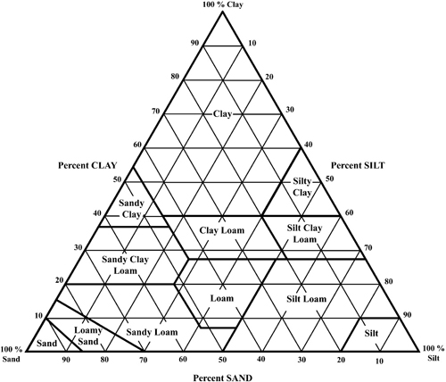
Figure 2-1. USDA soil texture triangle.
In summary, gradation of the soil used at the septic system effluent dispersal site should be between clay and gravel and should be well graded. Sites that are not ideal for septic systems have cobble at ground surface, consist of sticky clays, or have shallow soil depth or restrictive soil layers.
Informal Instructions for Estimating Soil Texture by Feel
The feel and appearance of the textural groups illustrate factors used to determine the texture of a soil in the field; feel and appearance also assist in field classification work. Forming a cast of soil, both dry and moist, in the hand and pressing a moist ball of soil between the thumb and forefinger constitute two major field tests to judge soil texture.
Soil texture can be estimated by feel using the procedure and key in Figure 2-2. Place approximately 25 grams of soil in the palm of your hand. Add water drop by drop and knead to break down aggregates. The soil has reached the proper consistency when it is plastic and moldable like moist putty.
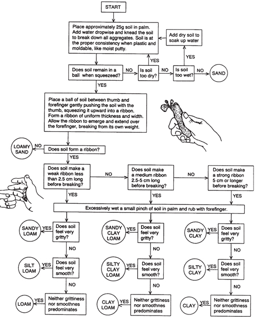
Figure 2-2. Procedure and key for estimating soil texture by feel.
Sand: Individual grains can be seen and felt readily. Squeezed in the hand when dry, this soil will fall apart when the pressure is released. Squeezed when moist, it will form a cast that will hold its shape when the pressure is released but will crumble when touched.
Sandy loam: Consists largely of sand, but has enough silt and clay present to give it a small amount of stability. Individual sand grains can be seen and felt readily. Squeezed in the hand when dry, this soil will fall apart when the pressure is released. Squeezed when moist, it forms a cast that will not only hold its shape when the pressure is released but will withstand careful handling without breaking. The stability of the moist cast differentiates this soil from sand.
Loam: Consists of an even mixture of sand and silt and contains a considerable amount of clay. It is easily crumbled when dry and has a slightly gritty yet fairly smooth feel. It is slightly plastic. Squeezed in the hand when dry, it will form a cast that will withstand careful handling. Squeezed when moist, the cast can be handled freely without breaking.
Silt loam: Consists of a moderate amount of fine grades of sand, a small amount of clay, and a large quantity of silt particles. Lumps of silt loam in a dry, undisturbed state appear quite cloddy but can be pulverized readily; dry, pulverized soil feels soft and floury. When wet, silt loam runs together and puddles. Either dry or moist casts can be handled freely without breaking. When a ball of moist soil is pressed between the thumb and forefinger, it will not press out into a smooth, unbroken ribbon but will have a broken appearance.
Clay loam: A fine-textured soil that breaks into clods or lumps and that is hard when dry. When a ball of moist soil is pressed between the thumb and forefinger, it will form a thin ribbon that will break readily, barely sustaining its own weight. The moist soil is plastic and will form a cast that will withstand considerable handling.
Clay: A fine-textured soil that breaks into very hard clods or lumps when dry and is plastic and unusually sticky when wet. When a ball of moist soil is pressed between the thumb and forefinger, it will form a long ribbon.
The soil texture key should be tested for samples within one’s own region. Soil materials behave in different ways depending on the shape and size of the sand fraction and the mineralogy of the clay fraction. Some sand fractions are flat in shape and will feel smooth (mica particles for example). Fine and very fine sand will behave in a manner similar to silt-sized particles. Clay fractions with appreciable smectite minerals will form long ribbons even with less than 40% clay.
Soil Structure
Soil structure is an important factor in a soil’s ability to treat and dispose of wastewater. Soil structure relates to the bigger picture of how water will move in the soil. While texture describes the diameter of soil particles, soil structure describes the shape of soil peds, which are themselves formed from individual soil particles in pedogenic processes. Soils with a good texture may be foiled by a poor structure. Some soils, such as sandy soils, lack structure because the peds do not form larger groups when the soil is in place or when it has been gently disturbed. You can also think of structure as a brick house in which the brick, mortar, and cement are the particles (i.e., texture) and the completed house is the structure.
We are concerned about structure because of its relation to land use. Certain soil structures are more likely to restrict water movement and are thus unsuitable for wastewater treatment and dispersal. Take, for example, a soil with a structure that does not allow roots to penetrate deeply into the soil.
Structure, if it exists, will enhance the flow of water through the soil. However, deeper soils (bottom of B horizon and deeper) tend to not have structure, and if they do have structure, the wastewater may damage the structure. A conservative approach is to base long-term hydraulic loading rate on soil texture alone and not take advantage of any benefit that might be claimed due to soil structure. This is a judgment call on the part of the decision maker.
Descriptions of structure (as with texture) follow the NRCS description categories. NRCS uses three general groups for classifying soil structure: natural soil structural units (pedogenic structure), structureless, and artificial earthy fragments or clods. We will spend the majority of time discussing the first two. Soil structure is described using three components: type, size, and grade.
Pedogenic structure is divided into seven types: granular, angular blocky, subangular blocky, platy, wedge, prismatic, and columnar (Figure 2-3). Soil peds with a granular structure look like granola and are most often found in the surface layers. The faces of angular blocky peds are often the same size; the faces are at sharp angles and the peds fit together well. Subangular blocky peds are more rounded than angular. Platy peds are wider and longer than they are deep, and often lie parallel to the soil surface. Soils with a wedge structure have elliptical, interlocking peds that often show slickened sides. Prismatic structure peds are, as the name implies, prism-shaped and vertically elongated. Columnar structure peds are similar to prismatic, but the ped tops are frequently rounded and bleached due to the high salt content.
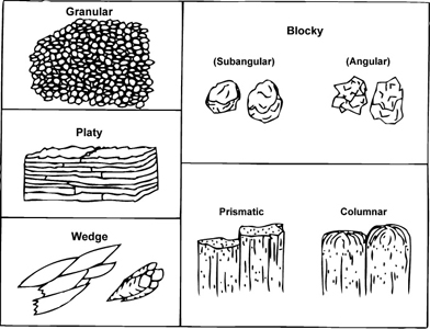
Figure 2-3. Soil structure.
Structureless soils are broken into three official groups: single grain, massive, and massive rock controlled fabric. Single grain refers to soils that lack structure and that are composed of at least 50% single grains, such as sand. Massive refers to any soil that sticks together but does not break apart into any predictable and repeatable type or shape (i.e., is structureless). Massive rock controlled fabric is used for soil developed from saprolite (chemically weathered rock). Unlike simple massive structure, the minerals in rock controlled fabric have a preferred orientation, and these soils may be easily broken into the individual mineral grains. Artificial structure is structure created by disturbance. In regards to onsite systems, this may be detrimental because it often will restrict water movement.
Size is broken into five groups: very fine (very thin), fine (thin), medium, coarse (thick), and very coarse (very thick). The actual size ranges vary depending on the type of structure. Note that platy refers to thickness while columnar and prismatic refer to diameter.
Grade refers to how well expressed or how stable the structure is. Structure is graded on a scale of 0 to 3. All structureless soils have a grade of 0; other soils range from 1 to 3. Structureless soils have no observable discrete units in place or in a hand sample. Weak-structured soils have units that are barely observable in place, and when disturbed the soil breaks into a mixture of whole and broken units. Moderate-structured soils have well-formed units that are evident in place, and when disturbed the soil breaks into a mixture of whole units and a few broken units. Strong-structured soils have units that are distinct in place and separate cleanly into whole units when disturbed. A compound structure occurs when smaller structural units form larger structural units. For example, a soil may be described as having “moderate coarse prismatic structure parting to strong medium subangular blocky structure.” This means that subangular blocky is the primary structure and prismatic is the secondary structure.
There has been less research into the formation of structure in soils than the importance of soil structure for land use or water management. Much of the latter research has to do with tillage and surface layers; these studies are concerned with both formation and destruction of structure as it relates to agronomic concerns. Similarly, research on salt-affected soils deals with how soils disperse and structure is destroyed. Finally, research on vertisols and expansive clay has shown how structures vary in veritsol regions. By reviewing these studies, we can get a general idea of how soil structures are formed.
Structure formation is related to physical, chemical, and biological processes at work in the soil. The physical processes that affect structure are illuviation/eluviation, freeze/thaw, compaction, disruption (mechanical or natural slope movement), and wet/dry–shrink/swell. Eluviated zones generally have weaker structure or are structureless, while illuviated zones show stronger structure because the illuviated material helps define the structural units by coating and stabilizing peds. Even if the material does not have a high amount of expandable clay minerals, desiccation will cause cracks to form. These cracks may become stabilized as clay, oxides, or organic matter moves through and/or coats them. When expandable clays are present, their action can help define and form wedge structure.
In regions that experience freezing of the ground surface, the freeze/thaw action may aid in structural development. In some ways this is similar to shrink/swell in that the soil is compacted as objects are forced upward. The compaction forms ped faces that, if stabilized, may form structural units. However, the next freeze/thaw cycle could destroy the original feature. Compaction generally results in denser soils that may even be structureless. Compaction due to farm implements or traffic will often result in a platy plow or traffic pan. If present, these should be disrupted throughout the drainfield as they could channel water into the trenches. If left alone, temporary perching (a localized high water table) may occur. Water may flow across the pan and into the disturbed area of the trenches. During construction, the backhoe may smear the sidewalls of the trench, resulting in decreased infiltration and poor performance. In soils with clays subject to smearing, construction should be limited to times when the soil is dry, or the backhoe bucket should be equipped with raking teeth to break up the smearing.
Slope movement can disrupt structure or prevent it from forming. Although some soils may have enough clay to qualify as an argillic horizon, there may not be clay coatings present since constant creep allows only a weak subangular blocky structure to form. This phenomenon also illustrates that time is a factor in structure formation since the older, more stable soils will have a better-developed structure.
Soil water chemistry affects structure as well. As with physical influences, these effects can be both positive and negative. Flocculation is the process of bringing particles close together, and is enhanced by polyvalent cations (Al+3, Ca+2, etc.). The flocculated units may form some of the initial building blocks for structural units.
Iron oxides may coat and bridge particles. These oxides may be attached to clay or other particle charges, and may help define a weak subangular blocky structure. Like oxides, organic acids will also coat and stabilize. Often these acids will overwhelm the particles and cement the particles in the horizon together.
Biological influence generally enhances the soil structure. Microbes and fungi add to structure with their byproducts and their mediation of redox reactions (Fe oxides), and by binding particles together. This phenomenon is most common in the A horizon (topsoil), but can occur wherever enough carbon is present for food. Plant roots can also be important in structure formation. In weak-structured soils they create larger pores. The pores may be reused and may coalesce to form ped faces. Root exudates help stabilize the pores. Bacteria and other microbes consume the exudates and further stabilize the ped faces and pores. Root growth physically compresses the voids. In well-structured soils, the roots follow the path of least resistance. Large roots can cause bypass flow. Insects may act in a similar way to roots; ants and termites can form stable channels. Other large organisms can produce effects similar to insects.
Soil structure should be a factor in land use management since structure plays an important role in water and gas movement in the soil. In onsite wastewater management, structure plays a significant role in water movement and in determining the long-term hydraulic acceptance rate (LTAR) by the soil evaluator. As the soil goes from granular to platy and massive, the structural porosity decreases, thus decreasing conductivity (Figure 2-4).
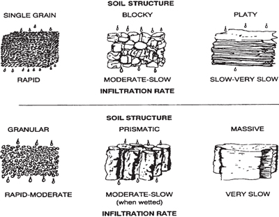
Figure 2-4. Soil structure and water movement.
The type of structure has a profound impact on how water will move through the soil. In dealing with a septic system, the water flow under the trench must be unsaturated through aerobic soil for proper treatment to occur. However, water moves out from the trench into the soil by saturated flow. This means that flow out of the trench bottom is at first controlled by the structural macropores. Flow from the trench is not a simple one-dimensional flow. Side walls only play a role to the depth at which they are ponded. Once flow leaves the zone of saturation it becomes unsaturated flow. Although matric potential can draw the flow in any direction (highest potential to lowest potential), the majority of the flow is still vertical. Once the water/effluent reaches the groundwater (or a restrictive layer) the flow will become driven by a hydraulic gradient, which is generally lateral. A well-structured soil will conduct water away faster because the larger voids will have a greater conductivity and may allow for deeper flow. Further, flow or diffusion of air (oxygen) will be enhanced by the better structure, thus improving treatment.
As with any evaluation, once the field work is done the real work begins in regard to interpretation. The LTAR is based on textural group first, which gives the range. Next, the LTAR is adjusted for structure. Finally, the LTAR is adjusted for other factors (e.g., subgrade).
In conclusion, structure is an important but overlooked aspect of soil evaluation. If possible, structure should be viewed in a pit. Structure should be assessed in the field with an eye for how water will flow through the soil; this can best be done by looking at roots and ped faces. The relationship between structure and water movement is complex and differs depending on moisture content.
Soil Mineralogy and Consistence
Evaluating soil consistence helps refine our understanding of how water and wastewater may move through the soil. Soil consistence, which can be estimated using simple physical tests, is used to estimate the shrink-swell capacity of the soil and thus its mineralogy. Aspects of consistence are used to determine if the horizon or soil will have a low permeability. Consistence is the degree and kind of cohesion and adherence that soil exhibits and/or the resistance of soil to deformation or rupture under applied stress. Moisture content strongly influences soil’s consistence. There are five ways to record consistence in the field: rupture resistance, manner of failure, stickiness, plasticity, and penetration resistance. Each characteristic measurement is recorded at specific moisture contents or within given moisture content ranges, which results in a measure of the strength of the soil to withstand an applied stress. Separate classes are made for blocks, peds and clods, and surface crusts and plates. Moisture content is also considered, and is classified as either dry or moist. Cementation classes are obtained by submerging overnight air-dried samples for at least 1 hour before the test. When measuring rupture resistance or penetration resistance using your finger, you must calibrate your fingers against known standards in order to estimate the force being applied.
Rupture resistance is a measure of the strength of soil material to withstand an applied stress. Different classes are provided for dry and moist block-like specimens (Table 2-4). The block-like specimen should be 1.0 to 1.5 in. (2.5–3.0 cm) square. The specimen is compressed between the thumb and forefinger, between both hands, or between a foot and a non-resilient flat surface. If a specimen resists rupture by compression, a weight is dropped onto it from increasingly greater heights until it ruptures. Failure occurs at the initial detection of deformation or rupture. Stress applied by hand should be over a 1-second period. Soil materials with a moist rupture resistance class stronger than Firm are considered limiting for onsite wastewater treatment.
Table 2-4. Rupture Resistance Classes for Block-Like Specimens
| Dry Class | Moist Class | Operation | Stress Applied* |
| Loose | Loose | Specimen not obtainable | |
| Soft | Very friable | Very slight force between fingers |
<8 N |
| Slightly hard | Friable | Slight force between fingers |
8–20 N |
| Moderately hard | Firm | Moderate force between fingers |
20–40 N |
| Hard | Very firm | Strong force between fingers |
40–80 N |
| Very hard | Extremely firm | Moderate force between hands |
80–160 N |
| Extremely hard | Slightly rigid | Foot pressure with full body weight |
160–800 N |
| Rigid | Rigid | Blow of <3 J but not body weight |
800 N, < 3 J |
| Very rigid | Very rigid | Blow of >3 J | >3 J |
| * Both force (newtons, N) and energy (joules, J) are used. A newton is equal to the amount of force required to give one kilogram an acceleration of one meter per second; there are approximately ten newtons in one unit of kilogram-force. One joule is the energy used to move a one newton force one meter. Three J is the energy delivered by dropping a 2 kg weight 15 cm. | |||
Manner of failure is the rate of change and the physical condition soil material attains when subjected to compression. Manner of failure is dependent upon water state; soil materials are moist or wetter (Table 2-5). To evaluate the manner of failure, a block-like specimen 1.0 to 1.5 in. (2.5–3.0 cm) square is pressed between the thumb and forefinger and/or a handful of soil material is squeezed in a hand.
Table 2-5. Manner of Failure Classes
| Class | Criteria |
| Brittle | Block ruptures abruptly (pops or shatters) |
| Semi-deformable | Block ruptures before compression to <1/2 original thickness |
| Deformable | Block ruptures after compression to >1/2 original thickness |
| Non-fluid | No soil flows through fingers with full compression |
| Slightly fluid | Some soil flows through fingers after full pressure, most remains in palm |
| Moderately fluid | Most soil flows through fingers after full pressure, some remains in palm |
| Very fluid | Most soil flows through fingers after gentle pressure, very little remains in palm |
| Non-smeary | At failure, block does not change abruptly to fluid, fingers do not skid, no smearing occurs |
| Weakly smeary | At failure, block changes abruptly to fluid, fingers skid, soil smears, little or no water remains on fingers |
| Moderately smeary | At failure, block changes abruptly to fluid, fingers skid, soil smears, some water remains on fingers |
| Strongly smeary | At failure, block changes abruptly to fluid, fingers skid, soil smears and is slippery, water easily seen on fingers |
Samples that are fluid and/or smeary present potential problems for onsite wastewater systems. They may be unstable (flow) or result in excessively smeared sidewalls during installation.
Stickiness is the capacity of soil material to adhere to other objects (Table 2-6). In a feel test, stickiness is estimated at the moisture content that displays maximum adherence between thumb and forefinger.
Table 2-6. Stickiness Classes
| Class | Criteria |
| Non-sticky | Little or no soil adheres to fingers after release of pressure |
| Slightly sticky | Soil adheres to both fingers after release of pressure with little stretching upon separation of fingers |
| Moderately sticky | Soil adheres to both fingers after release of pressure with some stretching upon separation of fingers |
| Very sticky | Soil adheres firmly to both fingers after release of pressure with much stretching upon separation of fingers |
Plasticity is the degree to which puddled or reworked soil material can be permanently deformed without rupturing (Table 2-7). The evaluation is made by forming a roll (wire) of soil at a water content where the maximum plasticity is expressed. This field test is usually performed by rolling a sample of soil between the hands and observing the length and thickness of the roll formed. The moderately plastic and very plastic soils are a potential problem for an onsite wastewater dispersal system.
Table 2-7. Plasticity Classes
| Class | Criteria |
| Non-plastic | Will not form a 6 mm diameter roll; or, if formed, cannot support itself if held on end |
| Slightly plastic | 6 mm diameter roll supports itself; 4 mm diameter roll does not |
| Moderately plastic | 4 mm diameter roll supports itself; 2 mm diameter roll does not |
| Very plastic | 2 mm diameter supports itself |
In order to understand the role clay mineralogy plays in consistence—and thus water movement—we must understand some of the properties of the clay minerals. Essentially, as consistence increases (i.e., as soil sticks together more) the rate of water movement decreases. This relation to water movement is due in part to the mineralogy of the clay component of the soil. Silica tetrahedrons (SiO4) have four sides, with four oxygen ions (O−2) surrounding one silica ion (Si+4). Aluminum octahedrons have eight sides, with six oxygen ions surrounding one aluminum ion (Al+3). Silica tetrahedrons and aluminum octahedrons are the basic building blocks of soil minerals, and they can be bound together into different layers by sharing their oxygen ions. The 1:1 clays are like an open face sandwich with one silica tetrahedron binding to one aluminum octahedron. The main 1:1 mineral is kaolinite. The 2:1 clays are like a sandwich with two slices of bread: Two silica tetrahedrons (bread) to one aluminum octahedron (filling). The 2:1 clays can be broken into two groups: non-expansive and expansive. In the non-expansive 2:1 clays, the sheets or layers are held together so strongly that neither water nor changes in ionic charge cause them to swell. The expansive 2:1 clays are bound together by very weak hydrogen bonds, which are easily broken; these minerals will swell upon wetting. Smectites, including bentonite, are one group of expansive clays. The role of soil parent material is paramount in the formation of clay minerals (a secondary product of weathering). The 1:1 minerals are usually weathered from acidic or felsic parent materials. The expanding 2:1 minerals are usually weathered from basic or mafic parent material. Parent material plays the biggest part in determining whether the soil will be expansive.
Chapter 3: Septic Systems
Introduction to Septic Systems
A septic system consists of a septic tank and drainfield. Both units have important treatment functions in these small-scale onsite wastewater treatment systems. This chapter will discuss the conventional septic system.
The purpose of the septic tank is to provide the first stage of treatment in onsite and decentralized wastewater systems by promoting physical settling, flotation, and anaerobic digestion. Additionally, the tank allows 1) storage of both digested and undigested solids until they are removed and 2) flows to another pretreatment component.
Traditionally, “Big Pipe” centralized wastewater treatment is designated as primary, secondary, or tertiary, which indicates the expected effluent quality. Primary treatment generally refers to a separation process for removal of settleable or floatable solids; in a septic system, this occurs in the septic tank. Secondary treatment generally refers to the removal of soluble organic material and an associated reduction in biochemical oxygen demand and total suspended solids; this occurs in the soil below the drainfield in a septic system.
Historically, tertiary treatment has referred to the removal of nutrients. Currently, the term is used to refer to the removal of parameters other than those removed in primary or secondary treatment processes or disinfection. A variety of technologies can be combined in a treatment train to obtain the desired effluent quality.
Unfortunately, it is difficult to verify, monitor, or control the level to which biological treatment occurs below the drainfield. In restrictive or environmentally sensitive sites where secondary or tertiary treatment is critical, mechanical treatment is used to ensure a sufficient level of treatment. Technologies that typically provide secondary treatment include aerobic treatment units and media filters, which are discussed in Chapters 4 and 5, respectively.
Microbial Treatment Processes
Treatment processes generally use microbes to remove contaminants. The type of microbe that will be prevalent in any treatment process is related to the presence or absence of free oxygen. Thus, one of the ways we categorize processes is by the microbes used in the process, which are categorized by the availability of free oxygen in the microbes’ native environment.
- Anaerobic microbes cannot survive with free oxygen in the system. Treatment by these organisms is relatively slow and inefficient, but the process generates approximately 1/10 of the solids an aerobic process will generate. The final products include odor, hydrogen sulfide, methane, and organic acids. The process is not stable if alkalinity is insufficient to buffer the organic acids generated. The effluent typically requires further treatment before discharge to a receiving environment.
- Aerobic microbes require free oxygen in the system. Aerobic treatment or decomposition is efficient and fast, leading to final treatment products that are less objectionable than with anaerobic treatment. Aerobic microbes are good at reducing the organic matter (biochemical oxygen demand, BOD) in wastewater.
- Facultative microorganisms can transition between an aerobic and an anaerobic (oxygen-free) environment.
- Anoxic microorganisms utilize oxygen that is associated with other atoms (e.g., NOx, FexOy, MnxOy, SOx). These organisms are critical in nitrogen removal by denitrification.
The active microbes in many wastewater treatment applications are facultative. Biological nitrogen removal processes integrate both aerobic (nitrification) and anoxic (denitrification) treatment processes. Both suspended (activated sludge) and attached (biofilm) growth aerobic processes are highly effective and efficient at treating effluents.
Physical Treatment Processes
Septic tanks separate solids from wastewater by settling heavier solids and floating fats, greases, and lighter solids. The solids content of the wastewater is reduced by 60 to 80% within the tank. The settled solids are called sludge, the floated solids are called scum, and the liquid layer in between is called the clear zone (Figure 3-1). Although the liquid in the clear zone is not highly treated, it is greatly clarified compared to the wastewater entering the tank because the larger particles have migrated to either the sludge or scum layers. Another important function of the septic tank is storage of these accumulated solids. The tank should be large enough to hold solids until maintenance (i.e., tank pumping) is performed.
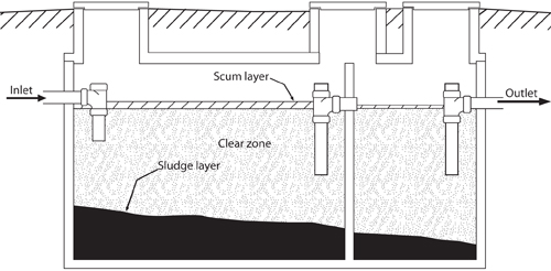
Figure 3-1. Cross section of a two-compartment septic tank showing sludge, clear zone, and scum layers.
The effluent, or wastewater that leaves the septic tank, should come from the clear zone to prevent solids from reaching the downstream components of the system. The baffle, T, or effluent screen at the outlet is designed to draw from the clear zone while leaving floatable and settleable solids in the tank. The settling process takes time, so the tank must be large enough to retain the wastewater in a turbulence-free environment for many hours; a typical retention time is 1 to 4 days. Excessive flow and turbulence can disrupt the settling process. Tank volume, size, shape, and inlet baffle configuration can all be designed to minimize turbulence.
Biological and Chemical Treatment Processes
Anaerobic and facultative biological processes in the oxygen-deficient environment of the tank provide partial digestion of some of the wastewater components. These processes are slow, incomplete, and produce odor. Septic solids include both biodegradable and non-biodegradable materials; although many of the solids will decompose, some solids will accumulate in the tank. Gases such as hydrogen sulfide, methane, and carbon dioxide that are produced during anaerobic digestion in the tank may create safety hazards for improperly equipped service personnel. The gases accumulate as bubbles in the sludge that, as they rise, may agitate or re-suspend settled solids. This will elevate the total suspended solids (TSS) concentration in the clear zone and ultimately send more suspended solids to downstream system components. This scenario often results when active digestion occurs during warm temperatures. Attempts to reduce discharge of re-suspended solids led to the development of tank features such as gas deflectors. Effluent screens now help to perform this function. The New Mexico Liquid Waste Regulations require the use of effluent screens, and it is recommended that any Tribal regulation also require these inexpensive additions to the septic tank. If an effluent screen is used, risers are required to provide ready access to the screen for routine maintenance.
The anaerobic digestion processes in tanks are affected by temperature; higher temperatures will enhance the rate of biological processes while lower temperatures will slow these processes. Certain substances also have an adverse effect on biological organisms and can reduce the rate of or halt digestion. Some factors that affect the way a tank functions include
- strength (concentration) of solids in the incoming wastewater;
- pH;
- introduction of harsh chemicals, drain cleaners, paint, photo processing chemicals, or other inappropriate substances into the waste stream, which may affect pH and biological activity;
- introduction of fat, oil, and grease (FOG);
- highly variable flow patterns that affect retention time;
- introduction of pharmaceuticals (especially those for chemotherapy and dialysis, long-term use of antibiotics, etc.) into the waste stream;
- introduction of process wastewaters, including regenerate from a water softener; and
- lack of maintenance that causes excess accumulation of solids, which in turn reduces effective volume and retention time.
Septic Tanks
A septic tank is a pretreatment component consisting of a buried tank designed and constructed to receive and partially treat raw wastewater from the source where it originated. The septic tank pretreatment reduces the quantity of solids contained in the effluent, protecting downstream components from plugging. The tank is either a one- or two-compartment tank made of concrete, fiberglass, or plastic (polyethylene, ABS); see Figures 3-2 and 3-3. In New Mexico, two-compartment tanks with inlet and outlet baffles are required. Most jurisdictions prohibit the use of metal tanks because they corrode. The New Mexico Environment Department (NMED) prohibits the use of cinder block as a tank material because the joints do not stand up to being continuously submerged. Tanks serving single-family residences are typically 1,000 to 1,500 gallons. These tanks are prefabricated and delivered to a site. Tanks serving larger facilities are usually 1) constructed in place; 2) manufactured and delivered in two pieces, either the top and bottom halves (clam-shell) or the tank and the lid; 3)constructed of a lighter material such as fiberglass and delivered in one piece to the site; or 4) a series of smaller tanks delivered to the site. The tank may be rectangular, oval, or cylindrical. The tank usually has an inlet baffle or T that is several inches higher than the outlet to ensure a flow gradient through the tank. The purpose of the inlet is to 1) direct the flow downward so as not to disturb the scum and 2) dissipate the energy of the flow to prevent turbulence and the resulting disturbance of solids, as well as minimize short-circuiting (where wastewater flows through the tank faster than expected). Some states do not require an inlet baffle or T because of concerns that it may plug. The tank has an outlet baffle or T extending into the liquid depth to draw the effluent from the clearest portion of the tank while leaving the scum in the tank. The outlet baffle is either outfitted with an effluent screen or, on an older tank, may have to be upgraded to accept an effluent screen. Most experts agree that a two-compartment septic tank will remove greater quantities of solids than a one-compartment tank.
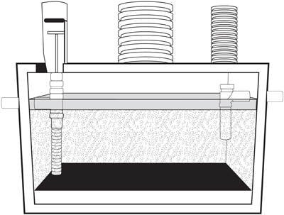
Figure 3-2. Typical one-compartment septic tank. (B. Lenning, 2003)
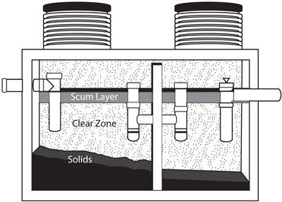
Figure 3-3. Typical two-compartment septic tank. In this tank, penetration of the center baffle is a PVC wall penetration with a “T” on either side (an extension that rises above the scum layer). (B. Lenning, 2003)
Raw wastewater flows into the tank and in most cases is diverted downward. The tank separates and retains settleable and floatable solids suspended in the raw wastewater in as calm an environment as possible. The settleable solids fall to the bottom and form the sludge layer. Some of the solids will float to the top as they are carried by gas bubbles produced during anaerobic digestion in the sludge. The lighter materials, including grease, float to the top and form the scum layer. Solids are retained in the tank for at least 48 hours as facultative and anaerobic organisms break down some of the wastes into dissolved fatty acids and gases. Total solids are reduced and a relatively clear effluent is discharged to the next downstream component.
Gases generated during this treatment process are usually vented back through the building’s plumbing stack vent. The environment within a septic tank is extremely hazardous due to a lack of oxygen and the presence of potentially toxic and explosive gases, such as hydrogen sulfide and methane. It is critical that this “confined space” environment be respected. A person involved in operations and maintenance should NEVER place their head within the zone impacted by gases from the septic tank environment.
A septic tank is the most commonly used pretreatment unit for onsite wastewater treatment systems. The septic tank can be used alone or in combination with almost any other treatment and/or dispersal/discharge component; septic tanks can and should be used as part of the treatment train in any onsite treatment system. Many advanced treatment system manufacturers state that a septic tank in front of their advanced treatment unit will starve the advanced unit of carbon. However, it is common in all larger treatment plants to perform primary treatment (i.e., separation and digestion of solids) prior to secondary treatment. The septic tank provides primary treatment at a reasonable cost, it does not require an energy source, and it is compact, simple, and inexpensive compared to most other pretreatment options.
A properly operating septic tank is expected to produce effluent with the following characteristics:
- 30 to 50% reduction in BOD (effluent BOD ~ 150 mg/L);
- 60 to 80% reduction of settleable and suspended solids;
- some removal of pathogens, though millions of microorganisms still typically exist in 100 ml of effluent; and
- 10 to 30% reduction in total nitrogen, with conversion of most organic nitrogen to ammonium nitrogen (NH4-N).
Septic Tank Design Considerations
As noted earlier, while some jurisdictions allow one-compartment septic tanks, most require a two-compartment septic tank, with the first or primary compartment typically consisting of 1/2 to 2/3 of the total liquid volume. The American Society for Testing and Materials (ASTM) C1227-08 (Standard Specification for Precast Concrete Septic Tanks), International Association of Plumbing and Mechanical Officials (IAPMO) PS 1-93 (Material and Property Standard for Prefabricated Septic Tanks), and Canadian Standards Association (CAN/CSA) B66-05 (Prefabricated Septic Tanks and Sewage Holding Tanks) are standards that have been developed for septic tanks. All standards are subject to change and should be checked to verify current requirements. When developing liquid waste regulations at a Tribal level, these standards can be referenced by name, reducing the burden of reproducing and updating the entire standard within the text of the regulation.
The National Pre-Cast Concrete Association (NPCA) offers a “best practices” manual and video. In general, the tanks must be durable and watertight. Leakage out of the tank (exfiltration) may contaminate groundwater. Infiltration of groundwater into the tank may inhibit the functioning of the tank and hydraulically overload the downstream components. The ASTM, IAPMO, and CAN/CSA standards, as well as the NPCA manual, contain instructions for conducting tests for watertightness.
Inlets, Outlets, and Baffles
Cast in place, flexible inlets and outlets can help maintain watertightness. ASTM C923-08 (Standard Specification for Resilient Connectors Between Reinforced Concrete Manhole Structures, Pipes, and Laterals) is a standard for such devices. Any seams or joints should also be watertight. ASTM C990-08 (Standard Specification for Joints for Concrete Pipe, Manholes, and Precast Box Sections Using Preformed Flexible Joint Sealants) is a standard that exists for materials to be used for such purposes. Inlet and outlet baffles are necessary to help the tank achieve its function. These baffles should be made of non-corrodible material; concrete baffles tend to dissolve above the liquid level line due to corrosive hydrogen sulfide gas produced during digestion, which subsequently forms sulfuric acid on the concrete surfaces.
For multiple-compartment tanks, there are a variety of methods to allow flow between the compartments; see Figures 3-3 and 3-4 for examples. Increasingly, tanks are being installed with risers to final grade to allow easy access for monitoring and maintenance activities. These should be watertight and properly constructed to prevent unauthorized or accidental entry. Many jurisdictions require gas deflection mechanisms below the opening in the outlet baffle/T to deflect solids away from the outlet.
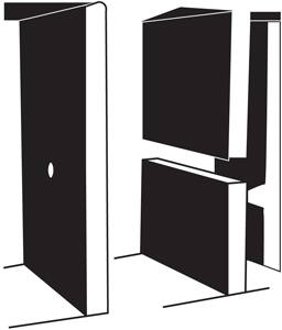
Figure 3-4. Optional methods used for inter-compartmental flow. (B. Lenning, 2003)
Baffles are structures placed around the inlet or outlet pipe that serve to direct incoming flow to or draw flow from the clear zone. They are made of various materials. Baffles extend only part of the way to the top or to the bottom of the tank (Figure 3-3).
Curtain baffles (Figure 3-5) are partial walls usually constructed of the same material as the rectangular tank that extend across the short dimension and down into the clear zone of the tank near the inlet or outlet port. In the past, curtain baffles and pipe Ts used as baffles were made of concrete or vitrified clay that had a tendency to deteriorate over time in the septic tank environment. With the availability of composite materials, curtain baffles are not often used in modern tank construction and have been replaced by Ts made of PVC as shown in Figure 3-5. As the name implies, these are T-shaped pipes attached to inlet and/or outlet pipes.
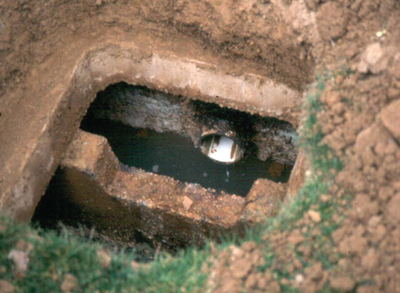
Figure 3-5. Concrete curtain baffle.
The use of a baffle or T at the inlet varies by regulatory jurisdiction. Where they are used, the devices direct incoming wastewater flow downward to the level of the clear zone, dissipating the energy of the incoming flow to prevent turbulence and disruption of the segregated solids in the tank. They may also prevent short-circuiting of flow across the top of an accumulated scum layer to the outlet.
Outlet ports of septic tanks may be fitted with sanitary Ts with drop pipes or with effluent screens. These are designed to retain floating solids in the tank. Outlet Ts should extend far enough above the wastewater surface and deep enough into the clear zone to keep the scum layer from entering the outlet port. The scum layer can float several inches above the water level, so extending the outlet baffle above the top of the outlet pipe 4 to 6 in. is recommended. It should penetrate to about 40% of the liquid depth. Access openings or risers should be located so that the inlet and outlet devices can be inspected and serviced.
Effluent Screen
As required by most recent liquid waste regulations developed in the United States, a device called an effluent screen (filter) is placed in the outlet T and is used in lieu of the outlet baffle or T or placed in a stand-alone unit following the tank (see Figure 3-6 for examples). The purpose of the effluent screen is to help keep solids in the tank and reduce the solids and organic loading on the drainfield. Effluent screens are designed to retain all solids greater than 1/8 in. in diameter, though some are designed to remove even smaller particles. Effluent screens are made of mesh, slotted screens, stacked plates made of plastic, or other material such as brush or fibrous material. Several types of effluent screens are available, including multiple plates assembled with slots between the plates, slotted cylinders, and multiple perforated tubes assembled together. Others may be fitted with an alarm or used in conjunction with a pump for pressurized applications (Figure 3-7). Although it is easier to install effluent screens in a new septic tank, several types can be retrofitted to existing tanks. In addition to models that can be placed directly into concrete baffles, installation options include (1) replacement of PVC outlet T or baffle with the effluent screen and housing, (2) placement in a sump outside the tank, or (3) placement within the pump vault of a pumped system.
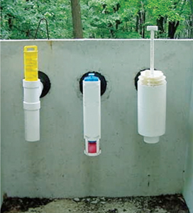
Figure 3-6. Some of the many proprietary effluent screens available.
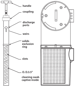
Figure 3-7. Two examples of many available outlet filters/screens. Source: U.S. EPA Manual, 2002
Some screens also have design features that help the tank mitigate flow surges, which allows the septic tank to act as an equalization basin for the drainfield. Hydraulic and/or biological overloading, as well as failure to service the tank and filter when needed, will cause the screen to plug. Floats and alarms can be added to detect when the liquid level is rising due to a plugged screen. The use of a float and alarm is highly recommended.
All effluent screens will require periodic service, including careful cleaning, and it is important to choose and install effluent screens with ease of serviceability in mind. Cleaning frequency depends on the overall size of the effluent screen unit, screen opening size, and use. A screen in the second compartment of a two-compartment tank should require less service than a screen in a one-compartment tank.
When cleaning the screen, care should be taken to prevent solids from flowing out of the outlet to downstream components. Some filters have features such as shut-off mechanisms or secondary screens that will prevent solids discharge, but if such a device is not included, some solids may be discharged downstream when the screen is removed, thereby reducing its overall effectiveness. One method of preventing this solids discharge is to pump down the tank level before removing the screen for cleaning.
If the scum layer is above the top of the filter, the liquid level must be pumped down before the screen is withdrawn; this will prevent scum from exiting the tank. Solids should be carefully washed from the screen back into the tank, preferably into the access opening on the inlet side of the tank. While some people claim that microorganisms establish residency on some of the filters, providing biological filtration and additional BOD reduction, the filters’ primary function has been the retention of solids.
In choosing and installing an effluent screen, the following factors must be considered.
- Effluent screens are designed to reduce solids discharge, not necessarily BOD discharge.
- The screen case should act as an outlet T.
- Screens should allow solids of no greater than 1/16 to 1/8 in. to pass through the cartridge, depending on system design and regulatory specifications.
- The filter cartridge should be secured in place and should not allow bypass of unfiltered solids if the screen openings become clogged.
- The effluent screen housing should be sized and placed so that it does not interfere with normal pumping of the tank.
- The estimated wastewater flow from the house or other source should be matched with the surface area of the filter (i.e., as the design flow increases, more surface area must be provided).
- An access opening at grade over the screen should be provided for screen removal and cleaning as needed (Figure 3-8).
- The design should include a mechanism to prevent solids bypass during cleaning.
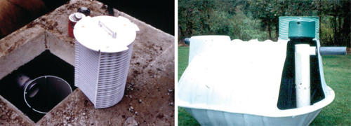
Figure 3-8. Housing for effluent screen located directly under tank opening (left). Cutaway tank showing position of effluent screen relative to attached riser (right).
Effluent screen design should maximize the amount of screen surface area to maximize solids removal and minimize cleaning frequency. In lieu of an effluent screen, some locations still use gas deflection mechanisms to deflect rising gasses produced in the sludge layer so that solids are not carried up the outlet T or baffle.
Septic Tank Installation Considerations
First and foremost, the tank must be installed level. Proper orientation of the tank inlet and outlet, as well as proper alignment of the top and bottom tank sections if two-piece tanks are being used, must be ensured. The tank must be located where it can be easily accessed for pumping, but away from drainage swales or depressions where surface water can collect. When placed in the excavated hole, it should rest on a level, granular base capable of bearing the weight of the tank, its contents, and the soil on top of the tank.
The inlets and outlets should be sealed to prevent exfiltration of wastewater and/or infiltration of surface or groundwater. These pipe penetrations should be made of flexible, resilient butyl rubber boots that are cast into the tank and allow a watertight seal around the pipe; as mentioned, ASTM C923-08 provides a standard for such devices. When mastic or bituminous grout is used to seal the inlet and outlet baffles, the probability of failure and leakage is extremely high. The pipes entering and exiting the tank should not only be watertight and structurally sound but also firmly supported by the soil around the tank to prevent shifting and movement of the pipe and breaking of the inlet and outlet seals. Manhole covers should be properly sealed to prevent infiltration of ground or surface waters through the manholes, yet removable to allow access for inspection and maintenance. If risers are used, both the lid and the riser-tank connection should be durable and watertight. The lid should also be locked or secured in such a way as to make access difficult for anyone other than the person responsible for checking the tank.
A field watertightness test is increasingly being required by local and state jurisdictions. As mentioned, ASTM, IAPMO, and CAN/CSA standards contain instructions for possible testing. Field testing methods for determining concrete strength, such as a Schmidt rebound hammer and a Windsor probe test, may be employed to ensure structural integrity of the tank.
Vehicular Traffic
Standard concrete septic tanks are not intended to be installed under vehicular traffic loads. However, concrete tanks designed for traffic loading or special situations are available. Among the applicable industry standards addressing design load requirements for concrete tanks is ASTM C857 (Standard Practice for Minimum Structural Design Loading for Underground Precast Concrete Utility Structures). Table 3-1 lists design criteria from Section 4 of the ASTM standard. When designing an onsite system that may be subject to some form of live load factors due to potential vehicular traffic, a designer must follow established engineering analyses, including such items as soil type, depth to groundwater, bedding materials, backfill materials, potential lateral earth pressures, and vertical loads. When designing onsite systems that have potential vehicular traffic, designers would benefit from referring to American Association of State Highway and Transportation Officials (AASHTO) HB-17, Standard Specification for Highway Bridges, 17th Edition. The IAPMO Standard for Prefabricated Septic Tanks (IAPMO PS 1-2004) states that “septic tanks and covers shall be designed for an earth load of not less than five hundred (500) pounds per square foot when the maximum coverage does not exceed three feet” (Section 4.7). There are many instances in New Mexico of plastic tanks being placed in trafficked areas and suffering structural collapse. When considering the use of tanks other than concrete in vehicular traffic areas consult with the manufacturer or a structural engineer. It is important to check and ensure that the standards being used are the most current available.
Table 3-1. Design Loads for Concrete Utility Structures (ASTM C857)
| Designation | Maximum Load | Typical Use |
| A-16 | 16,000 lbf/wheel | Heavy Traffic |
| A-12 | 12,000 lbf/wheel | Medium Traffic |
| A-8 | 8,000 lbf/wheel | Light Traffic |
| A-0.3 | 300 lbf/ft2 | Pedestrian Walkways |
Monitoring and Maintenance Considerations
In maintaining the small-scale wastewater treatment system, routine inspections should be made to
- monitor sludge and scum accumulations, especially at the outlet end of the tanks;
- check for structural soundness and watertightness;
- ensure that baffles, Ts, and effluent filters are in proper position and secured to the tank; and
- ensure that inlets, outlets, access risers, and lids are in good condition and properly sealed or protected.
There are a number of simple field observations to verify that the tank is functioning properly: odor, effluent characteristics (temperature, pH, dissolved oxygen, clarity), and proper stratification of the scum, sludge, and clear zone. It is also useful to keep track of past and present water levels in the tank, the “D-Box,” and the drainfield. Also, any backflow from the next downstream component indicates problems. Field monitoring hardware can be fabricated or commercially available products can be used. Many maintenance workers use either a “Sludge Judge”-type device or a stick and towel with a foot.
At some point the tank should be pumped. If a tank has been pumped, a more in-depth inspection of the tank’s structural integrity can be performed. Recommendations for when to pump differ considerably and include
- when the distance between the bottom of the outlet and the bottom of the scum or top of the sludge reaches a predetermined distance;
- when sludge and scum accumulations exceed 33% of the tank’s liquid volume;
- when the volume of the clear zone between the scum and sludge is less than one day’s design flow; or
- after some set, predetermined period of time (e.g., every 3 years).
Even if onsite treatment systems are properly sized and used, the set time interval option may produce excess septage that must be handled, which can increase ongoing maintenance costs unnecessarily. The set time interval option is only recommended for smaller (home) systems. It is further recommended that the interval be adjusted based on tank size and residential loading as presented in Table 3-2.
Table 3-2. Recommended Number of Years Between Pumpings of Septic Tanks According to Size of Tank and Household
| Tank Size (gal) | Household Size (number of people) | |||||||||
| 1 | 2 | 3 | 4 | 5 | 6 | 7 | 8 | 9 | 10 | |
| 500 | 5.8 | 2.6 | 1.5 | 1.0 | 0.7 | 0.4 | 0.3 | 0.2 | 0.1 | – |
| 750 | 9.1 | 4.2 | 2.6 | 1.8 | 1.3 | 1.0 | 0.7 | 0.6 | 0.4 | 0.3 |
| 1,000 | 12.4 | 5.9 | 3.7 | 2.6 | 2.0 | 1.5 | 1.2 | 1.0 | 0.8 | 0.7 |
| 1,250 | 7.5 | 4.8 | 3.4 | 2.6 | 2.0 | 1.7 | 1.4 | 1.2 | 1.0 | |
| 1,500 | 9.1 | 5.9 | 4.2 | 3.3 | 2.6 | 2.1 | 1.8 | 1.5 | 1.3 | |
| 1,750 | 6.9 | 5.0 | 3.9 | 3.1 | 2.6 | 2.2 | 1.9 | 1.6 | ||
| 2,000 | 8.0 | 5.9 | 4.5 | 3.7 | 3.1 | 2.6 | 2.2 | 2.0 | ||
| 2,250 | 6.7 | 5.2 | 4.2 | 3.5 | 3.0 | 2.6 | 2.3 | |||
| 2,500 | 5.9 | 4.8 | 4.0 | 4.0 | 3.0 | 2.6 |
Again, when performing these inspections or pumping the tank, it is imperative that you never enter the tank. If the tank must be entered after pumping to repair a baffle or crack, appropriate protective confined entry measures must be taken (as per OSHA). In addition, appropriate protective gear should be worn when performing inspection or maintenance activities on a septic tank or any of its subcomponents, including outlet filters/screens, because of potential exposure to pathogens and/or hazardous chemicals that may be in the sewage. What is appropriate may vary depending on jurisdiction, but, at a minimum, protective gear should include waterproof gloves, splash protective safety glasses, and droplet inhalation protection.
Access to the tank, including adequately sized openings, is required to ensure that proper monitoring and maintenance activities can be performed. Both chambers of a two-compartment tank should be pumped out whenever a tank is serviced. It is not necessary to leave any material in the tank to help “seed” the tank as this causes it to start functioning more quickly after pumping. When a tank is pumped, the septage pumped from a tank must be properly handled. As a regulatory entity, it is wise to require septage pumpers and haulers to maintain a record of cradle to grave manifests on all pumped septage. System owners may experience an increase in odors from the roof vents after having the tank pumped out, but this usually subsides after the scum layer in the tank has been re-established. Odor control devices, which use activated carbon to remove odors, can be retrofitted on vent stacks to help prevent this.
No independent studies have shown that septic tank additives provide any benefit to the septic system. Their use is neither recommended nor necessary. Rather, practicing water conservation, avoiding materials that may be harmful to the system, and implementing an ongoing monitoring and maintenance program should be stressed.
Grease Interceptors
The grease interceptor is used to remove grease and oil from the wastewater stream prior to further pretreatment so that downstream components don’t become plugged with grease and oil. The grease interceptor is also called a grease trap in some jurisdictions. They are designed to handle flows only from fixtures where fat, oil, and/or grease are generated. The grease interceptor consists of a specialized tank or a septic tank with some modifications to help retain grease and oil. Other jurisdictions draw a distinction between units that treat a water flow by cooling it and floating the grease and oil and units that capture grease to keep it out of the water stream. The distinction between these units is not clear in the language used universally in the industry, but the principal of capturing and separating the grease and oil as early as possible is recognized. The purpose of the unit is to provide time for the wastewater to cool; many references suggest a minimum retention time of one day. The grease trap typically consists of flotation chambers with no mechanical parts where fat, oil, and grease float to the water’s surface in the tank and are retained. The remaining liquid is then discharged to the next downstream component.
Grease interceptors are rarely used for individual homes. They are typically used to treat wastewater from sources containing high levels of fat, oil, and grease, such as commercial kitchens, restaurants, schools, cafeterias, convenience stores, and gas stations with food service facilities. Wastewater flows going to grease interceptors should not contain black water and other flows that typically do not include very high oil and grease concentrations. Wastewater temperature, solids concentrations, inlet conditions, retention time, nature of the grease and oils, and maintenance practices can all affect the performance of grease interceptors. They were initially designed for animal fats (lard) that are semisolid at normal room temperatures. Today, many liquid vegetable oils are used, which are liquid at room temperature, and grease interceptors have more difficulty removing oils.
Wastes that include degreasers and emulsifiers also affect the coagulation of grease and oil. The closer the grease interceptor is to the source, the warmer the temperature of the wastewater entering the tank may be. This may inhibit the floatation of fat, oil, and grease and the ability of the interceptor to retain them. Likewise, any surges or turbulence in the interceptor may result in the discharge of fat, oil, and grease from the interceptor. The goal should be to place the interceptor as far from a heat source as possible while still isolating the flow so it is not contaminated with other materials. The unit seen in Figure 3-9 shows a grease interceptor with inlets and outlets that extend deeper than in a normal septic tank. This unit is from a jurisdiction that draws a distinction between a grease separator and a grease interceptor. The extended baffles allow more storage volume for the grease and oil. Volumes for grease interceptors usually vary from one to three times the average daily flow of the facility, with a minimum recommended volume of 1,500 gallons. Grease interceptors require annual maintenance, at a minimum, and maintenance every 3 months is more common. Clearly, this is not an under-the-sink grease separator. IAPMO/ANSI Z1001-2007 (Prefabricated Gravity Grease Interceptors) and IAPMO PS 80-2008 (Clarifiers) are two standards available for grease interceptors.
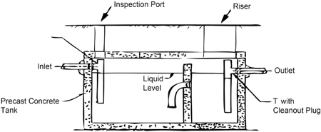
Figure 3-9. Typical grease interceptor/trap. (US EPA Manual, 1980)
Grease/Oil Separators
Grease/oil separators typically consist of small chambers that are plumbed into plumbing fixtures where grease and oil are found (kitchen sinks, dishwashers, etc.). Historically, there has been a problem with these mechanisms functioning properly. Much of this may be due to a low retention time because of their small volumes combined with the high temperatures found in the waste stream and periodic flow surges. Sensors are commercially available to help monitor sludge, grease, and scum levels in the separator. Discharge from a separator may remain in its own stream or may be combined with flows from the rest of the facility. Effluent screens for grease interceptors made primarily to help interceptors/traps retain fat, oil, and grease are commercially available. These are high-maintenance devices that need frequent servicing to prevent blockage of wastewater flows.
Drainfield and Distribution System
The drainfield performs secondary treatment of the effluent to remove soluble organic material and reduce BOD and total suspended solids (TSS). The soluble BOD removal is accomplished via microorganisms in the drainfield soils. The distribution system moves the effluent from the septic tank to the drainfield.
Principles of Soil Water Flow
Water is the main carrier for the transport of pollutants through soils. Therefore, knowledge of the water flow pattern and magnitude of the flow through the soil is essential for designing land-based waste disposal systems (e.g., septic systems), as well as for conducting environmental assessments.
Water moves through the soil as a result of forces acting on it. In general, and for most practical cases, the major forces that act on water in the soil are gravity (gravitational potential), attraction of solid particles to water, capillary suction of water in soil pores in the unsaturated zone (matric potential), and water pressure within the saturated zone (submergence potential). In the unsaturated zone, where soil pores are filled with both air and water, the matric potential is taken to be negative. In the saturated zone, where almost all the pores are filled with water, the submergence potential is taken to be positive. The submergence potential is the water pressure in the pore space caused by the column of water above the pore. If the pore location is 1 foot below the static water table, the submergence potential is 1 foot of water.
Water Flow Through Soils
Water flows in the direction of lower water pressure from the reference elevation (hydraulic head). The rate of water flow depends on the magnitude of the hydraulic gradient and hydraulic conductivity of the medium. For example, water is applied to one end of a horizontal soil column of known cross-sectional area under a constant hydraulic head, H1, and exits the other end of the column under a constant hydraulic head, H2 (Figure 3-10). Knowing the saturated hydraulic conductivity of the column and applying Darcy’s law, one can determine the quantity of water that can pass through the column during a specified time period. Conversely, knowing the flux and hydraulic gradient, one can calculate a saturated hydraulic conductivity based on the flow rate through the column. An instrument using this setup to measure conductivity is known as a constant head permeameter.
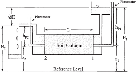
Figure 3-10. A schematic diagram of a soil column showing the total hydraulic head at the inlet (H1) and outlet (H2).
Saturated Flow
Generally speaking, continuous large pores and fractures in a soil conduct water at a faster rate than smaller-diameter pores or tight fractures. When the soil is saturated, most of the water passes through large tubular pores created by roots and animals or the planar voids between soil peds (often referred to as macropores). This is one reason soil structure is critical in understanding hydraulic capacity. Although the inter-particle pores, or pores inside soil peds (referred to as matrix pores), may be filled up with water, the rate of water movement is relatively slow in these pores compared to the macropores. Under saturated conditions, the hydraulic conductivity (i.e., Ksat) of the soil is a constant value at any given time for any given point within the soil body. Within a soil, Ksat varies from location to location (spatial variability) as well as in different directions (directional conductivity due to the anisotropic nature of soils). In addition to spatial and directional variability, Ksat may change with time (temporal variability) due to changes in temperature, antecedent moisture, and other factors. Any measured Ksat value represents an average conductivity of the volume of the soil under consideration.
Unsaturated Flow
During the drainage process of a saturated soil volume with no water input, water initially moves out of the larger pores due to gravity. Subsequently, water moves out of the smaller pores due to vertical drainage, plant root uptake, evaporation from the surface, and other factors. As water moves out of this volume of soil, the soil water content decreases and the tendency of the soil to hold water increases. Consequently, the flow path for water becomes narrower, and the ability of the soil to transmit water (represented by conductivity) decreases as the soil water content decreases. Mathematically speaking, the unsaturated hydraulic conductivity is a function of the soil water content or soil water pressure head.
Steady State and Transient Flow
The rate of water movement through a volume of a soil under a steady state condition is constant (i.e., does not change with time), whereas under transient conditions the rate of flow changes with time. For example, the groundwater flow is considered to be under steady state if it flows toward a natural drainage system at a constant rate with no change in the total hydraulic head or volume of saturation. Near a well that is pumped intermittently, on the other hand, the flow is under transient conditions. Another example is the transient condition in the unsaturated zone around the trenches of a septic system with no ponding, or around the emitters of a drip system receiving wastewater intermittently (with each dosing cycle).
Infiltration and Soil Water Profile
Water may enter the soil under a variety of conditions. Under a rainfall event or a spray irrigation system, water is applied to the soil surface fairly uniformly in a relatively large area. In an infiltration gallery, water is applied to the soil in a relatively small area. Water applied to a trench enters the soil through the bottom and perhaps sidewalls of the trench. Under any of these conditions, a general pattern for the soil water distribution with depth (referred to as soil water profile) can be established.
For example, when the rate of water application to the soil by a spray irrigation system in a relatively large, flat area equals or exceeds the maximum rate of water infiltration into the soil, the zone immediately below the soil surface becomes saturated (and ponding may occur); this zone is called the saturation zone (Figure 3-11). The volume of the soil below this saturation zone is referred to as the transmission zone. In this unsaturated zone, soil water content is fairly uniform (for a uniform soil). At the end of the transmission zone is the wetting zone where water content decreases rapidly with depth. At the leading edge of the wetting zone (referred to as wetting front) the hydraulic gradient is relatively high, mainly due to matric potential, and the wetted zone advances into the dry soil rather rapidly despite the low unsaturated hydraulic conductivity of the zone.
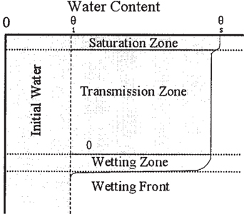
Figure 3-11. A schematic diagram showing the soil water profile with depth during the infiltration of water into an initially moist uniform soil.
Infiltration Rate, Cumulative Infiltration, and the Effect of Initial Soil Water Content on Infiltration Rate
The rate of water entry into the soil from a surface (e.g., surface of the land, bottom or side of a trench) is referred to as the infiltration rate. The infiltration rate into a dry or moist soil decreases with time mainly due to an increase in soil water content and a decrease in hydraulic gradient. If infiltration continues, the rate of water entry into the soil reaches a constant value (steady state condition) that is considered to be the same as the saturated hydraulic conductivity of the soil volume near the infiltrative surface. The total amount of water entering the soil since the start of infiltration is referred to as the cumulative infiltration. The slope of the flat portion of the cumulative infiltration curve after the soil has been wet for a long period of time is the final infiltration rate.
The infiltration rate depends on the amount of water in the soil. The wetter the soil, the lower the initial infiltration rate.
Runoff Occurrence
Runoff occurs when the rate of rainfall (or water application to the soil) exceeds the final infiltration rate. Using the infiltration curve for a given initial soil water content, the amount of runoff can be estimated based on the rate and duration of the rainfall or other wetting event.
Application to Onsite Systems
What does it all mean? In a typical septic system, wastewater containing dissolved and suspended pollutants is applied to the drainfield area. Whether wastewater is applied to the drainfield by gravity (e.g., conventional septic system) or by a distribution system using a pump (e.g., low-pressure pipe or low-pressure distribution system), the volume of wastewater entering the trenches daily must infiltrate the soil and move away laterally from the drainfield or percolate vertically to a deep aquifer within each 24-hour period. Otherwise, ponding in the trenches and eventual surfacing of effluent may occur, and/or soil in the drainfield area may become saturated, preventing the wastewater from being treated by soil in the drainfield area.
In a septic system where wastewater is applied to the trenches by gravity feed, wastewater generally enters the beginning of each trench. If the rate of wastewater application exceeds the infiltration capacity of the soil in the first few feet of a trench, ponding occurs and wastewater runs down along the trench in a manner similar to runoff (Figure 3-12). As ponding occurs, the infiltrative surface increases, but is always limited to the wetted perimeter along the bottom and sidewalls of the trench. If wastewater reaches the end of the trench, ponding has occurred throughout the length of trench; this is referred to as a mature biomat. This biological clogging mat (biomat) reduces the infiltration capacity of the soil in the trenches, which results in a greater depth of ponding. Ponding and eventual formation of a biomat can also occur in systems in which wastewater is dispersed over the entire drainfield in doses, as in low-pressure pipe (LPP) systems.
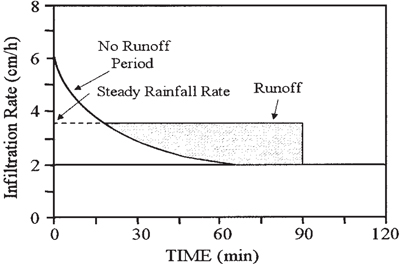
Figure 3-12. The infiltration rate and the amount of runoff generated at a site for a 90-minute uniform rainfall event.
Once wastewater enters the soil from the bottom and sidewalls of the trenches (or from emitters in a drip system), it moves away from the trenches due to a hydraulic gradient that is created by the application of wastewater. If the rate of wastewater application exceeds the capacity of the soil to transmit the added water vertically under unsaturated conditions, the soil becomes saturated. A saturated soil does not generally provide treatment for wastewater; therefore, it is undesirable for the saturated zone to reach the bottom of the trenches within a prescribed distance (referred to as separation distance). In general, water in a saturated zone created below the bottom of the trenches must move laterally away from the drainfield. In flat areas, movement of water occurs as a result of the formation of a mound of water under the drainfield, which increases the lateral hydraulic gradient, resulting in water movement. In sloping areas, the cumulative effects of the land slope and potential mounding determine the hydraulic gradient. Based on Darcy’s law, other factors that determine the magnitude of the lateral flow from the drainfield are the saturated hydraulic conductivity of the saturated zone, the product of the thickness and width of the saturated zone (i.e., the cross-sectional area or window through which lateral flow occurs), and the presence of limiting layers. Figure 3-13 presents a schematic diagram of the cross-sectional view of a septic system on gently slopping ground, showing the movement of water in the unsaturated and saturated zones in the drainfield area.
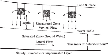
Figure 3-13. Schematic diagram of the cross-section of three trenches installed on a gently sloping ground, indicating the requirement for knowledge of the minimum depth of unsaturated zone below the trenches. Also shown is the thickness of the saturated zone where lateral flow occurs.
Purpose of the Drainfield
The purpose of the drainfield is twofold: it disposes of partially treated effluent into the soil and completes treatment in the drainfield soil. The first step of treatment occurs in the septic tank, and the final biological treatment of the wastewater occurs in the soil beneath the drainfield. The septic tank produces a cloudy liquid that still contains pathogens and pollutants. This septic tank effluent flows into the drainfield trenches and then trickles through the soil; the soil adsorbs the pathogens, such as viruses, which are then destroyed by soil microbes. The soil can also adsorb and hold certain chemicals, including phosphorus, some forms of nitrogen, and many complex organics. A microbe rich zone called the biomat forms in the soil/trench interface, which consists of the 1 to 6 in. of soil below the trench bottom. This biomat zone is where the majority of the biological treatment takes place. Excess organic loading or excessive solids accumulation in the septic tank from neglecting the pumping of the tank can cause the trench to accumulate an excessive biomat. When this happens, the biomat clogs the soil and reduces the outflow of water from the trench, causing the trench to fill with effluent. Eventually the effluent will surface on the ground, resulting in a failed system
Historically, septic system drainfields have been rock and pipe systems. These rock trenches are typically 12 to 36 in. wide and 12 to 60 in. deep, with 12 to 36 in. of rock in the trench. The pipe in the trench is typically 4 in. in diameter, with two holes with diameters of 3/8 to 1/2 in. drilled periodically along the pipe at 4 and 8 o’clock. There are also a number of proprietary “gravel-less” products available that replace the rock and pipe in the trenches, including plastic louvered chambers, dense polystyrene aggregate, tire chips, structured plastic media, or large-diameter pipe covered in fabric. The purpose of all of these materials is to provide space in the trench to allow distribution of the effluent to the trench bottom.
Regardless of what is in the trench, the soil under the trench treats and disposes of the effluent. For this reason, a septic system can only be used in soils that will adequately remove the contaminants from the effluent. If a septic system is installed in soil that is not appropriate, a number of things may occur. In a soil that slowly transmits the effluent, effluent will seep out onto the soil surface above the drainfield or back up into the home. In a soil that transmits the effluent too rapidly, the water may pass too rapidly downward and enter the groundwater untreated. The escaping sewage can cause an unpleasant smell and may pose serious health problems. If the soil can absorb the effluent but not treat it, or if the trenches are installed directly into groundwater or bedrock, the sewage may contaminate the groundwater with pathogens or toxins. Because the underlying groundwater serves as the source of drinking water for your well and your neighbors’ wells, it is very important that the system be installed in the proper soil conditions and that the septic system is correctly sized, installed, operated, and maintained.
Drainfield Distribution Options
There are a number of common strategies for applying or distributing septic tank effluent to an infiltrative surface, and there are many variations on how each application and distribution option is used locally. The following brief summary will focus on two broad classifications of application/distribution: gravity flow distribution and dosed flow distribution. Several distribution network design options will be discussed for each.
Gravity Flow Distribution
Gravity causes water to flow downhill, and septic tank effluent is no exception. Effluent flows by gravity from one component to the next; for example, wastewater flowing into the septic tank displaces effluent in the tank, which then flows from the tank to the next component, such as a drop box or a drainfield. The outlet of one component (e.g., a pretreatment device) must be at a higher elevation than the inlet of the next downstream component or the flow will pond, settling solids and possibly plugging the pipe. If the receiving pretreatment or final treatment/dispersal component has multiple distribution lines or laterals, this component should include a mechanism for distributing the flow to each of the lines/laterals. This can be a series of leveled Ts or a distribution box.
Under a gravity flow scenario, the flow is intermittent throughout the day depending on when wastewater is generated; this is referred to as a “demand dosed” or “socially dosed” system. This type of system is frequently favored because it is the least expensive and requires the least amount of maintenance.
Social dosing results in frequent effluent discharge rates too low to flow uniformly throughout the downstream pretreatment or dispersal components, especially the infiltrative surface of the drainfield. This results in non-uniform distribution of wastewater to the soil treatment system, with most of the flow occurring in localized areas of the infiltrative surface. This is especially problematic in coarser-textured soils since effluent may not spend sufficient time in the soil to receive proper treatment until a biomat forms. Then, unless properly managed, the biomat may continue to develop until the treatment component can’t handle the inflow any longer and the component either backs up or the effluent surfaces.
The traditional rock and pipe system’s piping network typically consists of 4-in. plastic pipe made of smooth wall polyvinyl chloride (PVC), flexible corrugated polyethylene (PE), or acrylonitrile-butadiene-styrene (ABS) that is perforated with one or two rows of holes or slots at or near the bottom. The piping that transmits effluent from one component to the next is not perforated. The primary purposes of the piping network include
- assisting in moving effluent throughout the length of trenches and beds;
- allowing an open bypass around sludged rock, soil infiltration in rock, and root blockages; and
- encouraging redistribution of effluent in a trench or bed.
Typically, the maximum length of any one lateral allowed by regulation is 150 ft. This restriction arises from the difficulty in controlling grade over the entire length of a very long lateral. Historically, this maximum length was 100 ft, but with the advent of laser levels it has steadily become longer.
When standard drainfields are discussed, mounded drainfields are often given as the alternative. A mounded drainfield is a modification of the standard drainfield that is completely above ground. There is actually a series of potential drainfield elevations, as shown in Figure 3-14. If the drainfield uses native soil to treat and disperse the wastewater and is simply lifted to achieve an acceptable separation from groundwater, the system is designed as a standard drainfield, but is higher in the soil profile. If the system is high enough to require soil replacement for the treatment portion of the drainfield, it should be designed as a mounded system.
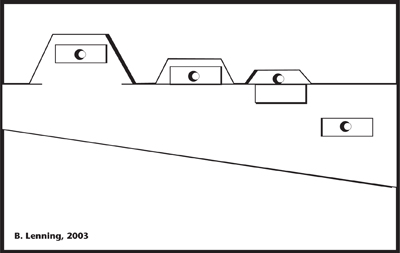
Figure 3-14. Progression of systems as soil depth decreases.
Gravity Distribution Options—Parallel Distribution
Parallel distribution is the common technique in most areas. It consists of a network of laterals of equal length designed to receive flow by gravity from a pretreatment component and then to distribute flow (also by gravity) to the infiltrative surface of a pretreatment or final treatment/dispersal component (Figure 3-15). Typically, wastewater flows via a 4-in. diameter non-perforated pipe from the upstream pretreatment component to a distribution box, which then divides the flow between the parallel laterals.
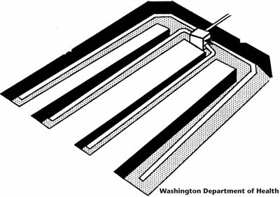
Figure 3-15. Typical layout for a parallel distribution network.
Distribution boxes are one of the most frequently used components in onsite treatment systems. The distribution box is a flow-splitting device designed to 1) receive wastewater flowing by gravity from a pretreatment component and 2) distribute equal flows to each distribution line or lateral in the next downstream component. It is typically a shallow box made of concrete, plastic, or fiberglass with one inlet and two or more outlets. All openings are usually 4 in. in diameter, with the outlet inverts (pipe bottom) at the same elevation. See Figure 3-16 for an example of a typical distribution box.
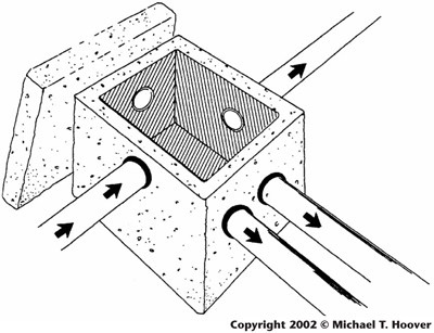
Figure 3-16. Typical distribution box.
In theory, septic tank effluent flows into the box through the single inlet, and the box is designed so that equal amounts of effluent flow out of each outlet. Unfortunately, because of a variety of factors, such as uneven settlement of the box, material getting hung up on the outlet, or an extremely low flow rate, equal flow to each trench or lateral usually does not occur. Invert leveling devices are commercially available to try and equalize the flow from each outlet. Some commercially available distribution boxes have leveling capabilities built into the box. Even if equal flow to each lateral is achieved, flow does not occur uniformly throughout the length of the lateral because of elevation variation and the effects of low flow caused by social dosing.
By design or by actual operation, flow can be directed to one lateral. When the receiving infiltrative surface cannot handle the inflow any longer, the flow can back up into the distribution box and flow out of another outlet. When operated in this way, a distribution box operates similarly to a drop box, which is discussed later as part of serial distribution. To prevent surges from flowing out one outlet, many distribution boxes have features such as baffles, Ls, or slotted inlet plates to break the surge. The distribution box does have a lid, which historically has been buried and inaccessible. A watertight riser should extend to the ground surface to facilitate monitoring and maintenance.
The box must be installed level to increase the potential for equal flows from each outlet. Some installers will even set it on a level concrete pad or compacted stone. The lids, inlets, and outlets should be sufficiently watertight to prevent any surface or groundwater from infiltrating the box.
When practical, the distribution box should be pumped out when the septic tank is pumped, should be cleaned out periodically, and should provide access for collecting a sample of effluent and for making direct observations of 1) flow distribution, 2) the clarity of the effluent going to the next component, or 3) whether the next component is backed up. Many studies have shown the deficiencies of distribution boxes, and, as a result, distribution box systems are not permitted or promoted in some local regulations or codes. For smaller systems, New Mexico allows leveled Ts to be used in place of distribution boxes. In addition, there are other flow-splitting devices, such as Ys, headers, and a variety of proprietary flow splitters, flow dividers, and weir boxes available; a leveled T is portrayed in Figure 3-17. Usually, a few feet of 4-in. diameter non-perforated pipe extending out of the flow-splitting device connect to 4-in. perforated pipe out of which the effluent flows onto the infiltrative surface. Flow-splitting devices must be separated from the trenches or bed with solid earth dams to prevent short-circuiting of effluent around the outside of the device.
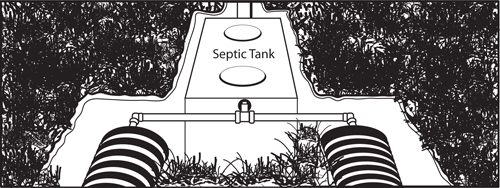
Figure 3-17. The leveled T is an alternative flow-splitting mechanism for parallel distribution networks. (Courtesy Infiltrator, Inc.)
If the receiving component is located at a higher elevation than the pretreatment component, effluent may be pumped to the distribution flow-splitting device; this is referred to as a pumped gravity system.
Parallel distribution drainfields are usually used on sites with slopes of less than 5%, though some local regulations/codes allow them on greater slopes, with each lateral at a different elevation (an example is shown in Figure 3-18). On relatively flat topography, the flow-splitting devices can operate as drop boxes (discussed under serial distribution) if one or more laterals can no longer handle the flows to them, allowing flow from one lateral to another. As slopes become greater, this capability becomes unavailable because effluent will surface rather than back up to the flow-splitting device. Thus, serial distribution is frequently required on steeper slopes when using gravity distribution.
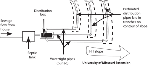
Figure 3-18. Parallel distribution network with laterals at different elevations.
In a system with significant slope, each lateral will follow the contour lines, with the bottom of the lateral being flat. Multiple laterals served by the same flow-splitting device are required to be of equal length if they are part of a parallel distribution network because each lateral is designed to receive the same amount of effluent. From an environmental protection/treatment point of view, it is important to understand that even if equal quantities of effluent flow into the beginning of each lateral, uniform distribution of the effluent throughout the length of each lateral does not occur. Many jurisdictions try to overcome distribution problems by using a distribution network of multiple laterals at the same elevation in which the piping is connected or looped (Figure 3-19).
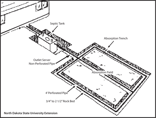
Figure 3-19. Typical loop distribution network in a bed.
The flow-splitting device should be accessible for ease of monitoring and maintenance. Monitoring and maintenance activities include assessing whether flows to each lateral are equal, shutting off one lateral if it has been overloaded, observing effluent quality, and collecting a sample if required. Because parallel distribution systems can experience problems distributing equal flows from traditional flow-splitting devices to the laterals, there are jurisdictions that limit the use of parallel distribution systems.
Gravity Distribution Options—Serial Distribution
A serial distribution network is designed to 1) receive flow by gravity from a pretreatment component and 2) sequentially distribute flow to laterals of a pretreatment or final treatment/dispersal component (Figure 3-20). The drainfield is composed of several laterals/trenches that receive wastewater in series. Under gravity distribution, gravity moves the wastewater down the slope of the drainfield. The drainfield is typically connected to the upstream pretreatment device by a 4-in. diameter non-perforated pipe that extends from the upstream component to the first lateral in the serial distribution network or to a drop box, depending on the flow control device that is used. A relief line is the flow device that causes effluent from one lateral to pond above the infiltrative surface to a predetermined elevation before it spills over to the next downstream lateral or treatment component (Figure 3-21). The relief line consists of solid, non-perforated, usually 4-in. pipe. In many jurisdictions, it is also called a step-down. Effluent flows into the uppermost lateral from the pretreatment unit. The relief line forces the effluent to pond in a trench before it will allow effluent to spill over to the next down-slope lateral, where the sequence begins again.
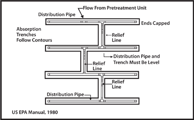
Figure 3-20. Typical serial distribution network without drop boxes.
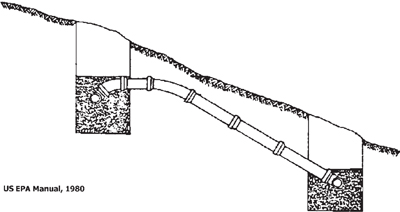
Figure 3-21. Typical relief line (step-down).
The relief line can be located anywhere along the lateral. The inlet elevation of the uppermost relief line must be at a lower elevation than the outlet of the preceding pretreatment component. The relief line must be installed on original soil so that no settling occurs that can change the elevations and no short-circuiting of flow can occur between trenches. The pipe specified for these systems must be of a minimum of schedule 40 pipe to resist crushing. There are no access points in the relief line to check that it is functioning properly; observation ports in each trench are needed to help determine if the system is operating correctly. A serious flaw in this system is that there is no capability to block the flow to any trench to allow the trench to rest, dry out, and recover.
A drop box is also a flow control device, but provides more control and options than a simple relief line. The box has one inlet, one or two outlets to a trench, and one outlet to the next down-slope drop box (Figure 3-22). The drop box is made of concrete, plastic, or fiberglass. The drop box may be located at the end or in the middle of the trench. The flow from the preceding pretreatment unit flows into the uppermost drop box.
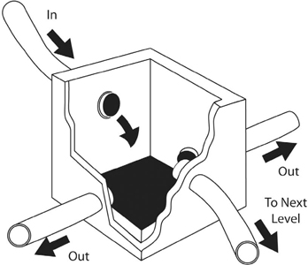
Figure 3-22. Typical drop box.
Liquid builds up in the drop box and flows out of the outlet(s) to the perforated laterals. As the uppermost laterals begin ponding because they cannot handle the entire daily flow, the liquid level in the drop box builds up to some predetermined point, causing it to spill through the relief line to the next down-slope drop box, where the sequence begins again (Figure 3-23).
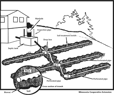
Figure 3-23. Serial distribution using drop boxes.
Again, as with the relief line, the inlet of the uppermost drop box must be at a lower elevation than the outlet of the preceding pretreatment component. Similarly, the inlet for each drop box must be higher than its outlet in order to discharge effluent to the next down-slope drop box. Drop boxes must be watertight to prevent infiltration of any surface or groundwater and must be placed on a stable base. There should be some undisturbed soil between the drop box and where the infiltrative surface in the trench begins. It is important that the lines between drop boxes be constructed so short-circuiting of effluent from the up-slope trench to the down-slope trench can occur. The drop box system should be installed with an access at final grade to facilitate monitoring and maintenance. The primary advantage of a drop box over a simple serial system is that one or more trenches can be taken out of service, which can create some semblance of an alternating system. This can be done either by plugging the drop box’s outlet(s) to the lateral you wish to rest or attaching a 90° L to the lateral outlet that rises above the invert level of the discharge to the next down-slope drop box.
The serial trenches are used to
- make full hydraulic use of the bottom and sidewall infiltrative surfaces;
- force the biomat to rapidly form on the infiltrative surfaces, reducing the period of time for concerns with saturated flows in the soil below the infiltrative surface;
- increase the hydrostatic head to assist in forcing water into the surrounding soils through the biomat that will rapidly form; and
- overcome the distribution problems encountered with a parallel distribution network.
The technique is usually applied on sloping sites (typically greater than 5%) so that there is a flow gradient from one trench to the next. However, they can be used on relatively level sites where laterals can be installed at elevation differences of at least 2 in., without the installation becoming too deep.
Unlike the parallel lateral system, each lateral in a serial system can be of a different length, giving the design professional some flexibility. However, the elevations of the laterals are critical, and there must be sufficient differences in elevation between laterals to allow wastewater to flow through the system. This technology is primarily used for septic tank effluent where a biomat will form quickly to provide unsaturated flow below the trenches; however, if the pretreatment component removes enough organics and solids to minimize the formation of a biomat, saturated flow may result, which will have an adverse impact on the treatment the soil provides. Some jurisdictions do not permit or encourage serial distribution systems.
Dosed Flow Distribution
A dosed flow distribution system uses a pump or other device to move predetermined volumes of effluent from a chamber (e.g., septic tank) out to the pretreatment or dispersal components. The dosing provides
- better distribution over the infiltrative surface than gravity flow distribution options,
- intervals between doses when drying and resting can occur,
- reductions in the rate of biomat formation,
- help maintaining unsaturated conditions in the treatment zones in soil,
- more uniform loading to pretreatment units such as media filters and aerobic treatment units (ATUs), and
- improved potential for uniform distribution over both space and time.
This technique can be used to distribute effluent in almost any application, using either a low-pressure pipe pumped system or a siphon system. This is the distribution method of choice for many. This method improves distribution, but it also adds either a mechanical or passive dosing device, which adds to both the initial cost and the need for increased monitoring and maintenance.
Ongoing monitoring and maintenance are very important, and alarms are necessary to indicate problems with the pump, circuitry, or rate of inflow. Alarms need to be audible and visible to system users, and supplied on a circuit separate from the pump circuit. Alarms that call operators or management entities are available. Other optional control panel accessories may be specified depending on the designer, and may include pump elapsed time meters, pump event counters, alarm event counters, surge protection, and remote telemetry. These accessories are very important operational trouble-shooting tools. For components like media filters, frequent, small doses (micro-dosing) are preferred over the historic 1 to 4 doses per day. However, especially with final treatment and dispersal components using pressure distribution, the doses should not be so frequent that they are not large enough to adequately pressurize the distribution network for the bulk of the dose cycle. If this happens, the uniformity of the distribution is reduced.
Demand and Timed Dosing of Treated Wastewater
With demand dosing, which is also referred to as “social dosing,” dosing occurs when a sufficient volume of sewage has been collected to activate the dosing device. The dose continues until the level that deactivates the dosing device has been reached. The pump-on and pump-off levels stay constant, and there is usually no control over how much effluent is dosed daily.
With a timed dosing system, an analog or digital timer (located in a control panel) controls the dosing device. The timer controls the number of doses per day (rest time between doses) and the dose volume (time the dosing device works). The pump-on and pump-off levels move up and down in the chamber, due to surges, though the distance between them remains the same. A larger chamber is required to allow for days with big flows. Timed dosing will allow a known volume of effluent to be distributed to the next downstream component every dose and every day. This results in considerable flexibility and control, but it is more costly and slightly more complicated than demand dosing. Since timed dosing effectively equalizes the flow, it protects downstream components from hydraulic overloading. When properly set up for a specific design waste flow, these systems can be used as an indicator of plumbing leaks and excess flows from a facility.
The timed dose control panels should be fitted with a pump override and/or a high level alarm. Timed dosing, in combination with a large equalization or storage tank, can be utilized by facilities that do not operate every day of the week, such as churches, flea markets, or race tracks. When properly designed, this may allow for a much smaller drainfield than would otherwise be required for peak flows on days of operation.
Dosing Devices
Pumps
The most common dosing device is the pump, and typically turbine and centrifugal effluent pumps are used (Figure 3-24). The pumps must be made to handle effluent or sewage. A single pump tank can dose to one or more independent networks using multiple alternating pumps or automatic valves. The pumps are located in a chamber with a sufficient volume to collect the proper dose volume; the chamber also contains other subcomponents that make the dosing system function properly. The pump can be part of either a demand or a timed dosing method, and can pump to pretreatment or dispersal components at higher or lower elevations.
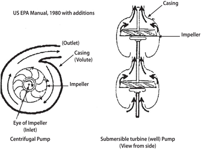
Figure 3-24. Typical pumps used in dosed flow distribution networks.
The other subcomponents of dosed flow distribution networks using pumps include
- the pump or timer that is controlled by floats or other mechanisms that operate on pressure differentials, and
- alarms, which are activated by floats or pressure differentials and indicate if there are problems with the pump, the power supply, or the volume of the influent.
Many of the subcomponents of a pump system are contained in a tank. In a timed dosed system, the pump tank is frequently called a surge tank or a flow equalization tank. The pump tank may be a separate tank or a separate compartment in a pretreatment tank. The pump tank should be watertight and be accessible at the final grade. Figure 3-25 depicts a typical pump tank.
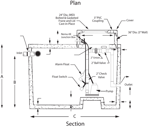
Figure 3-25. Typical pump tank.
When a pump tank is specifically designed as a surge or flow equalization tank, it is approximately the same size as the septic tank. When sizing a pump tank for flow equalization, the tank must be large enough for pump cycle storage, equalization volume, and at least 24 hours of emergency storage in the case of pump failure. Pump tanks are usually constructed similar to septic tanks; most are precast concrete tanks, and the same specifications regarding structural integrity and watertightness apply. A secure access riser must be provided above grade for monitoring and access for maintenance. The same functions are sometimes performed via a vault set into a pump tank or even into a one-compartment septic tank.
Siphons
Siphons are passive dosing devices that discharge a set amount of effluent when liquid levels in a chamber displace the air in the trap of the siphon (Figure 3-26). If a siphon is to be used, the system must be a demand dosed system. The siphon does not require power, and will only function if the pretreatment or dispersal component receiving the dosed flow from the siphon is several feet lower in elevation than the siphon discharge. To dose multiple systems, two siphons can be placed in a chamber. As with many passive systems, design, installation, and maintenance are all critical to proper operation.
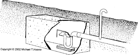
Figure 3-26. Typical siphon in a chamber.
Dosed Gravity Distribution
Pumps or siphons can be used to dose a gravity distribution system. The dosed gravity system is typically used where the component being dosed is located at a higher elevation than the pump dosing the system. In a typical dosed system, a pressure pipe is used to distribute the effluent over the entire soil interface. In a gravity dosed system, this advantage is lost since the pressure pipe simply discharges the effluent into the pipe at the head of the trench and allows it to run along the trench by gravity. The pump or siphon discharges a predetermined dose to a 4-in. perforated pipe network that is designed using one of the gravity flow distribution network options (Figure 3-27). This is the worst of both dosed and gravity distribution systems: It requires a dosing system and all of the associated maintenance, but does not provide the distribution and treatment advantages of the pressure dosed system. A dosed gravity system is not recommended since many of the advantages of a pressure dosed distribution network are lost due to the reduced uniformity along the trench caused by gravity distribution throughout the length of the piping network.
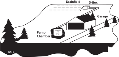
Figure 3-27. Typical dose to a gravity system.
Pressure Manifold System
A pressure manifold system consists of a several-inch diameter pipe (manifold) tapped with small-diameter outlet pipes, as shown in Figure 3-28. The small-diameter outlet pipes allow the manifold to become pressurized, which results in equal amounts of flow out of each outlet pipe. The small-diameter outlet pipes discharge to a typical gravity flow distribution network. The pressure manifold must be located at a higher elevation than the laterals to which it drains.
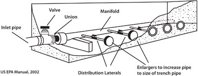
Figure 3-28. Typical pressure manifold. Produces uniform distribution of flow to laterals.
This dosed flow distribution option provides a more accurate and consistent division of flows to each of the gravity distribution pipes. In a pressure manifold system, flow in the piping network to the final treatment and dispersal trench or bed occurs by gravity; as a result, this method has similar shortcomings to gravity flow systems. Again, the piping network may consist of pipes in independent trenches or in a loop. Valves may be placed on each outlet pipe, providing the opportunity to rest or repair individual lines. In cold climates, the pressure manifold should be protected from freezing or designed to drain back to the dose tank. There are public domain and commercial products available that perform this function.
Pressure distribution is a method of distributing effluent to a pretreatment (such as a media filter) or final treatment/dispersal component that results in similar amounts of effluent being discharged to each square foot of infiltrative surface (Figure 3-29).
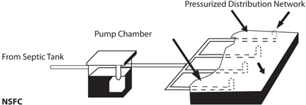
Figure 3-29. Typical pressure distribution network.
The components of a dosed flow distribution system provide the capability for dosing a predetermined volume and pressurization of the distribution network. The rate of delivery for the dosing device is measured in gallons per minute. The components are the transport line, force main, manifolds, valves, laterals, lateral turn-ups and cleanouts, and orifices in the laterals. The transport and manifold lines are typically 1 1/2 to 3 in. in diameter. The laterals are typically 1 to 2 in. in diameter; orifices are in the range of 1/8 to 1/4 in. in diameter and are typically oriented in the 6 o’clock or 12 o’clock position. The spacing of the orifices and laterals varies depending on how uniform the distribution must be. Typically, there are 4 to 15 ft2 of infiltrative surface per orifice.
In a dosed system, a predetermined quantity of effluent is collected in the pump tank, and at a predetermined volume or after a specified length of time a pump or siphon discharges the effluent to a distribution network. Because of the smaller-diameter pipe and orifices in a pressure manifold system, the distribution network pressurizes rapidly, allowing most of the dose volume to be discharged when the network is fully pressurized. The greater the uniformity of distribution by the network, the greater the uniformity of the loading on each square foot of infiltrative surface. This results in unsaturated flows in the soil or other media occurring at a shallower depth, which results in improved treatment.
A pressure dosed system is used where uniformity of distribution is vital, such as in a drainfield located in coarse or shallow soils or in a pretreatment process using a coarse media. Some locations require effective treatment at a shallower depth of unsaturated, permeable soil than would be practical with a gravity flow system; these systems use a pressure dosed system.
Design Considerations
Dosed flow systems are low-pressure systems, with typical residual heads of 2 to 5 ft. The design must ensure that the vast majority of a dose volume is discharged when the network is fully pressurized. Thus, steps should be taken to prevent effluent from being redistributed throughout the network when the system is pressurizing or after the dosing device has stopped discharging effluent.
Maximum differentials in flow from orifices at different locations in the distribution network exist to help ensure uniformity of distribution, but commonly used rules for these differentials vary across the U.S. Typical requirements are a maximum differential in the flow from any two orifices in one lateral of 10% and from any two orifices in the entire network of 15%. Careful design considerations must be taken when designing these systems on a sloping site since the elevation difference will aggravate the expected head loss-induced differences. The smaller the orifice, the higher the head loss through the orifice and the more uniform the flow out of the orifice. However, the smaller the orifice, the greater the potential for plugging. This is a balancing act—as orifice diameters approach 1/8 in., the required residual pressure is usually increased to increase velocities to help keep the orifices clean. It is recommended that the effluent quality be improved with a high-capacity effluent filter or pressurized filter prior to dosing the laterals.
The smaller the orifices and the greater their spacing, the faster the distribution network will pressurize, which will decrease the pump and dose volume requirements. When the orifices face the 12 o’clock position, the network will pressurize more rapidly. However, unless the system is designed to drain back to the pump chamber, as is routinely done in many cold weather areas, the orifices will plug more readily due to buildups of biological growth and standing effluent in the lateral, and this will require more frequent cleaning. When oriented in the 12 o’clock position, orifice shields or a perforated sleeve must be used.
Valves of different types (ball valves, check valves, etc.) have been increasingly used because they offer significant control and flexibility. However, they provide potential “weak points” if ongoing monitoring and maintenance needs are not met. Concerns with valves include that they may freeze and crack in cold weather areas, solids may get hung up on edges of the valves, and they provide a route of access by which someone may inadvertently or purposefully adjust the system hydraulics. Various motorized and non-motorized valves are available to split flows into two or more distribution networks to help keep the required pump or siphon capacity reduced.
Depending on the design professional’s choices and the area available, allowable lateral lengths can be much longer than those typically permitted for non-pressurized laterals. The pressurized systems can also be used to dose multiple trenches of unequal length. Using gravel-free chambers or a 6- to 12-in. pipe cut in half, with orifices spraying upwards, can result in more of the infiltrative surface area in a trench or bed being used. This improvement in efficiency is due to the spray from the orifice being spread out when the top of the chamber or 1/2 pipe is hit. Effluent filters are commercially available that filter solids under pressurized conditions. They are typically connected to the discharge of the pump when used.
Installation Considerations
The devices that activate the pump and alarms must be set properly. If valves (for example, ball or gate valves) are used to equalize flows throughout the distribution network, they must be properly adjusted as part of the installation process. Pressure testing of the network should be done to ensure that both the construction and design are accurate. Pressure testing can be done by checking the distal pressure.
Operation, Monitoring, and Maintenance Considerations
The functioning of the dosing device, the devices that control it, and the alarms must be monitored and maintained by a well-trained and certified professional. Determining drawdown times and distances, residual pressures, and the number of doses or pump-run time since the last inspection are routine activities during monitoring inspections. The laterals must periodically be cleaned out, so access to each individual line is critical. Failure to flush out laterals on a regular basis (sometimes as frequently as every 6 to 12 months) will result in orifice plugging and unequal distribution.
Drip Distribution
Drip distribution or drip irrigation is a pressure distribution network that delivers small, precise volumes of pretreated wastewater at slow, controlled rates (measured in gallons per hour) directly to the soil (Figure 3-30).
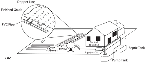
Figure 3-30. Typical drip line network layout.
A drip distribution system requires several mechanical components:
- A pump.
- A filter to remove solids bigger than 100 microns, such as a disk filter, spin filter, or pressurized sand filter.
- A pressure regulator for when a non-pressure-compensating (turbulent) emitter is used in the drip line.
- A controller or other mechanism that controls pump operation, alarms, and flushing of filters and lines.
- Drip dispersal components.
- A supply line and manifold, which extend from the pressurization device to a drip zone’s manifold and then to the drip lines that are arranged in one or more zones.
- Drip line (1/2-in. diameter polyethylene tubing).
- Emitters, which are devices with orifices in them that are embedded along the inside of the drip line at a set distance. There are two types of emitters: turbulent flow (non-pressure-compensating), out of which the flow increases as the pressure increases, and pressure-compensating, out of which the flow remains relatively constant as the pressure changes. Pressure-compensating emitters provide a more uniform distribution while under pressure than turbulent flow emitters; however, they are more expensive.
- Vacuum breakers/pressure relief valves to minimize the suction of soil into the pipe through the emitter when the pump shuts off.
- Return line and manifold to collect liquid from the drip lines and return the liquid to the pretreatment unit.
The treated wastewater to be delivered by the drip system is pumped from the pump chamber to the system. Preferably, this is done on a timed cycle. Depending on the system size and the design flow, there are usually two or more drip zones. Before the treated wastewater can be drip irrigated, the effluent must pass through a filter to remove solids so they will not plug the emitters. Some filters have back-flush mechanisms built in that help keep the filter open. A supply line takes the effluent and discharges it to one or more manifolds, each serving one zone. The manifold discharges the effluent to the drip lines in a zone. Effluent then flows out of the emitters directly into the soil. A valve on the return manifold is periodically opened, either manually or automatically, and effluent flushes the drip line to keep it and the emitters open. Effluent then flows into a return line carrying flow back to the pretreatment mechanism. Some designs will have individual return lines for each of the drip lines.
The drip distribution method is the most efficient for achieving uniform distribution. Drip distribution may be used anywhere pressure distribution or other distribution means are required or desired, including mounds and sand filters. Drip distribution may be used for sites not suitable for other systems because soils are too shallow or slowly permeable, as long as sufficient area exists. Because drip distribution is installed more shallowly, it uses more of the soil depth for treatment and doesn’t need any media around or below the pipe. Some locations will permit drip distribution to be used on more shallow soils than other methods of distribution. Drip distribution may be more useable than other methods on difficult sites, sites that are wooded or irregularly shaped, or sites that have steep slopes or compacted soils, and may be used for reuse applications, such as landscape irrigation. One advantage of drip distribution is that it causes less site disruption during construction.
Design Considerations
In any successful drip system, the effluent must be treated/filtered to reduce the potential for emitters to clog. Such systems also require a significant storage or equalization tank and timed dosing. In contrast to low-pressure pipe systems, the drip system requires high-head, low-flow pumps. Routine system functions (timed dosing, filter back flush, lateral flushing) can be performed manually, but are usually automated with electric solenoid valves and automatic controllers.
A certain depth of unsaturated soil is required below the drip lines to provide an adequate treatment zone below the pipe, but the usefulness of the available soil depth is maximized because there is no gravel below the pipe.
The hydraulic loading is expressed in terms of footprint area, as in gallons/day/ft2, over the entire surface area (i.e., not square feet of infiltrative surface), and design is based on gallons/emitter/hour. Long lateral runs are possible if needed; however, head losses due to friction are great because of the small diameter drip lines with their in-place emitters. Most manufacturers limit lateral length to approximately 250 to 300 ft.
Check valves are used to isolate zones if one common return line is used. In colder climates, it is recommended that the drip lines be placed a bit deeper, with a good growth of turfgrass established over them. Drip line networks have performed successfully in cold climates at installation depths of 6 to 8 in.
Installation Considerations
Drip line is commonly plowed or inserted into the soil with minimal disturbance of the soil. No media, such as gravel, is placed in the narrow drip line trench. This is a specialized activity, and the average installer will need different equipment and specialized knowledge to install this system. The drip lines are connected to the supply and return manifolds with flexible PVC pipe or tubing. A drip line should not be connected directly to a manifold since the potential for kinking is significant. The installation depth is typically 6 to 10 in., though the installation may be several inches deeper in areas with freezing concerns. After the initial installation in a cold climate area, mulch may be placed over the network, at least until the turfgrass is established.
Operation, Monitoring, and Maintenance Considerations
Manufacturers try to minimize the clogging of emitters with emitter design features, such as impregnating the drip line with a biocide. Whether treated or not, the drip lines must be flushed on a regular basis, either continuously or intermittently. Periodic measurement of residual pressures and water flow is important to check for emitter and filter clogging. Available recommended monitoring devices include pressure indicators and flow meters. Sensors are now available that allow managers to access system performance information via the Internet.
Chapter 4: Passive Advanced Treatment Systems
Media Filters
A passive treatment system is one that has few or no moving parts and requires very little operational intervention to successfully treat the wastewater. A media filter is an aerobic, fixed-film bioreactor, which is sometimes called a packed bed filter or biofilter. The fixed-film bioreactor has bacterial populations fixed to a media and, as a result, they are able to maintain a relatively-fixed population size, which leads to more stable treatment as long as nutrients and oxygen are available. In addition to being more stable, they are also lower maintenance. The media filter’s pretreatment process usually consists of a lined excavation or watertight structure filled or packed with some media to which microorganisms can attach themselves, in an aerobic environment, and treat wastewater as it passes through. See Figure 4-1 for a general drawing of a system using a media filter.

Figure 4-1. Typical system using media filter.
The media filter system consists of
- a container for the medium, which is usually either a lined excavation (most commonly lined with 30 mil PVC) or a watertight structure made of concrete, polyethylene, or fiberglass;
- a distribution and dosing system to ensure effluent uniformly passes by the microorganisms; and
- a filtering medium composed of varying depths of some type of medium to which microorganisms can attach.
A variety of media have been or are being used, including
- washed and graded sand or gravel,
- bottom ash from coal-fired power plants,
- foam chips and cubes (primarily in proprietary products),
- peat (primarily in proprietary products),
- synthetic textile materials (primarily in proprietary products),
- plastic shapes,
- anthracite,
- crushed glass, and
- expanded shale.
The media filter will also contain an under-drain system and other subcomponents, depending on the type of filter being used and the filter manufacturer.
The pre-treated (usually by a septic system) wastewater effluent is dosed (preferably time-dosed) out of the distribution network and flows slowly, in an unsaturated flow, downward through the filter medium. The wastewater must remain in the filter medium long enough for acceptable treatment, which often requires a recirculation system. The system can be either socially (demand) dosed or time dosed. In either case, the time between doses must be sufficient to allow re-aeration of the medium to ensure sufficient oxygen levels for aerobic microbiological treatment processes. Like a fixed growth aerobic treatment unit (ATU), bacteria attach themselves to a medium. Effluent passes through the medium and microorganisms provide the bulk of treatment.
Bacterial slimes created by microbial masses can absorb soluble and colloidal material, as well as wastewater microorganisms. In troubleshooting one of these systems, it is useful to realize that the treatment is by
- physical processes (filtering and sedimentation),
- chemical processes (adsorption of dissolved small colloidal constituents), and
- biological degradation of BOD and oxidation of ammonia to nitrate.
The filter can be designed so that the liquid flows through the medium just once or multiple times via recirculation. These flow options will be discussed in greater detail later in this section.
Media filters can provide a high level of relatively stable treatment. They are frequently used for single-family residences, small communities, and commercial facilities when higher levels of pretreatment must be provided because the soil has insufficient depth or is too coarse to provide adequate treatment, or when there is a need for higher levels of protection due to an environmentally sensitive site. They are also used on sites where sufficient area is not available for other components. They can provide a high enough effluent quality for irrigation in locations where surface application is permitted.
There are two common flow scenarios: single pass media filters loaded at 1.2 gallons per minute (gpm)/ft2 and recirculating sand/gravel filters loaded at 3 to 5 gpm/ft2 based on forward flow.
Single Pass Media Filters
In a single pass media filter, the effluent passes downward slowly in an unsaturated flow through the filter medium, is collected, and is then transmitted via either a gravity flow or a dosed flow distribution network to the infiltrative surface/medium in the next downstream component; this configuration is shown in Figure 4-2. The containment vessel follows a septic tank and a pump or siphon chamber. Although it is not recommended, a single pass media filter may be fed by gravity, but the recommended dosing method is a pressure or dripline distribution network. In general, the systems have 24 to 36 in. of media. The media used can vary widely from sand to gravel (2–4 mm), fabric sheets, fuzzy fabric balls, fabric squares, or foam cubes. Many of these are proprietary systems. Some are made of recycled material, while others are recycled objects like small plastic beverage bottles. A number of authors have discussed using glass chips or wood chips as a substitute for sand, and although these are presented in the literature, the experience base with them is limited and there is a risk associated with using these media materials.
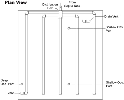
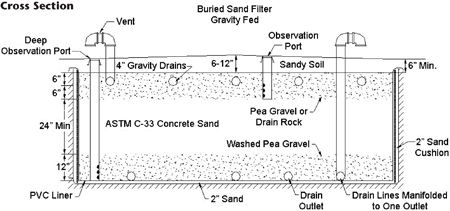
Figure 4-2. Plan and cross section typical buried gravity flow single pass sand filter.
Beneath the treatment media is a piping system (underdrain) that uses gravity to collect the treated effluent for transfer to the next component or to a vault in which a pump will transmit the effluent under pressure to the next downstream component. Single pass media filters are used for single-family homes, small cluster developments, and other relatively low-flow applications where nitrogen removal is not important. Because they typically have lower monitoring and maintenance requirements, provide greater reliability, and are more passive, a single pass media filter is often used instead of an aerobic treatment unit (ATU). In general, single pass media filters, such as a sand filter, remove fecal coliform better than ATUs. In some jurisdictions, single pass media filters have monitoring and maintenance requirements similar to an ATU.
Single pass media filter design should account for both hydraulic and organic loadings. The typical hydraulic loading rate is between 1 and 2 gallons/ft2/day. To provide sufficient retention time in the medium for suitable treatment, single pass media filters typically use finer media to slow down the flow. Dosing volume and frequency are important design elements. Historical dosing frequency has been four times daily; current recommendations are up to 12 to 24 doses per day. Media characteristics/types and distribution network characteristics limit the number of doses per day. The distribution method most commonly used is pressure distribution. Dripline distribution and pressure distribution with spray nozzles have also been used, especially if the filter has an appropriate enclosure. Filters may be buried or may be open (free access) to maximize aeration. Single pass media filters using peat, foam cubes/chips, or synthetic textile materials are usually free access, but they have covers to protect them from the elements and invasion by pests such as rodents. These filters may be below ground level or totally above ground.
In some jurisdictions, single pass sand and peat filters may be constructed with no liner on the bottom. This requires suitable soil and sufficient soil depth to transmit the treated effluent away from the filter. One version used in many jurisdictions is a sand-lined trench in which a typical drainfield with pressure distribution is lined on the bottom (and sides in some locales) with a certain depth of specific sand. This is usually done where soils are coarse and cannot be expected to provide much treatment. Because of the high quality of effluent from a single pass filter, many jurisdictions permit increases in loading rates for final treatment/dispersal components that receive the filter’s effluent.
One variation of a single pass media filter that is available is a stratified sand filter. Effluent passes through various grades of sand and gravel prior to being collected and transmitted to the next component. Bottomless single pass sand filters are generally buried under 6 to 10 in. of breathable soils that have been planted with grass. This type of filter treatment is used mainly for BOD5 (five-day BOD) and TSS reduction. Removal of fecal bacteria can be achieved to 3 or 4 log removal. Treatment as a whole is regarded as dependent on the hydraulic loading rate. A single pass sand filter can be constructed to look very much like a simple slow sand filter (Figure 4-3).
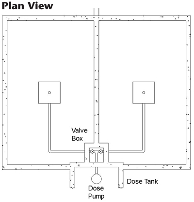
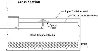
Figure 4-3. Plan and cross section of an above grade gravity single pass sand filter.
It is not always possible to construct the single pass sand filter as a gravity-fed unit. In this situation, it is very common to construct the system as a low-pressure pipe distribution system (Figures 4-4 and 4-5).
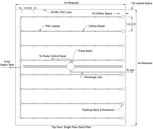
Figure 4-4. Single pass sand filter with a low-pressure pipe distribution system in plan view.
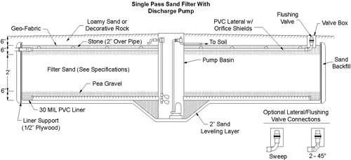
Figure 4-5. Single pass sand filter with a low-pressure pipe distribution system in cross section view.
Granular Media Filters
Recirculating Sand and Gravel Filters
In a recirculating (multiple pass) sand or gravel filter (RSF/RGF), effluent passes from a recirculating/dosing tank to the media filter and downward as unsaturated flow through the filter medium. The treated wastewater is collected and transmitted back to the recirculating/dosing tank where at least a portion of it is again pumped to the filter. Periodically, or routinely as part of every dose, some treated effluent flows to the next downstream component, as shown in Figure 4-6. The system consists of
- a recirculating/dosing tank, though some smaller units use a single two-compartment septic tank both for providing primary treatment and as the recirculating/dosing tank (see Figure 4-6);
- a distribution network;
- a filter bed;
- an underdrain system; and
- a return line fitted with a flow-splitting device that will return a portion of the filtered effluent back to the recirculating/dosing tank and the remainder to the next downstream component.
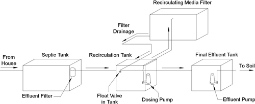
Figure 4-6. Recirculating sand/gravel filter schematic.
Unlike a typical single pass sand filter, the recirculating media filters have been used successfully to treat high-strength wastes as well as typical residential wastewater.
Details of the recirculation tank are shown in Figure 4-7. The RSF and RGF are frequently used where nitrogen reduction is important. Most small-scale wastewater treatment systems are intended to remove BOD5, i.e., carbon. However, there are times when nitrogen control is required. In a surface water discharge, it may be sufficient to convert urea (ammonia) to nitrate. In a groundwater discharge, it is frequently necessary to remove the nitrate. The first step (ammonia to nitrate) is called nitrification. The second step (nitrate to nitrogen gas) is called denitrification. Significant nitrogen reductions are possible because nitrified effluent returning to the recirculating/dosing tank from the filter mixes with septic tank effluent, creating the potential for denitrification. To ensure a denitrifying environment, some units recirculate effluent back through the septic tank. The media filters that use textile or foam media are also appropriate for extended removal of nitrogen. The nitrogen removal systems have a recirculating ratio between 3:1 and 5:1 within the filter for nitrification. The recycle ratio to an anoxic zone, such as a septic tank, is proportional to the dissolved oxygen, which should be measured regularly and kept below 0.5 mg/L dissolved oxygen to ensure maximum denitrification. The recirculation ratio for a recirculating sand/gravel filter is defined in Figure 4-8.
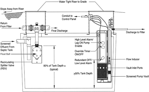
Figure 4-7. Detail schematic of a recirculation tank for a multiple pass media filter.
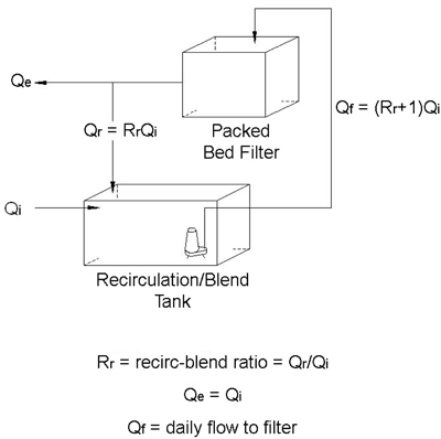
Figure 4-8. Recirculation ratio definition for recirculating sand/gravel filter without denitrificaton.
Figures 4-9 and 4-10 show two methods for splitting flow for recirculation. Figure 4-9 is a proprietary valve system that allows the flow to continue to recirculate for treatment until it must leave the system for dispersal to the environment. Figure 4-10 places a double slope on the bottom of the filter and in every pass sends a percentage of the flow for dispersal.
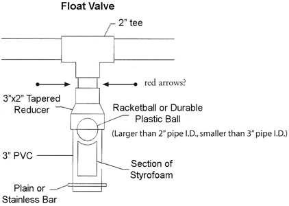
Figure 4-9. Proprietary three-way flow-splitting valve.
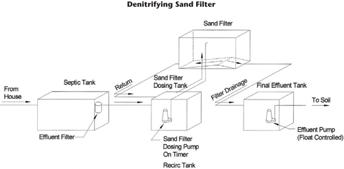
Figure 4-10. Double slope bottom for splitting a percentage of flow for dispersal on every pass.
If denitrification is an additional treatment goal along with nitrification, a recirculation loop to a carbon-rich anoxic environment should be added. One alternative is to recirculate back to the septic tank, which always precedes these units.
Because RSF/RGF filters typically have lower monitoring and maintenance requirements, provide greater reliability, and are more passive, they are often used instead of an aerobic treatment unit (ATU), which is a small activated sludge plant. Again, in some jurisdictions, recirculating media filters have monitoring and maintenance requirements similar to an ATU.
A timer controls the pump in the recirculating/dosing tank. These systems are dosed much more frequently than a single pass media filter. It is not unusual to have 48 to 96 doses per day, depending on the type of media and design. For mineral media, the medium is usually coarser than that used for a single pass filter. A typical multiple pass RSF/RGF will have a hydraulic loading rate of 3 to 5 or more gallons/ft2/day based on forward flow. For some media filters, the hydraulic loading rate may be much greater. Recirculation ratios typically range from 2:1 to 5:1 and can be changed depending on flows, giving greater performance control than exists for many other pretreatment units. Flow-splitting devices can be located inside the filter, inside the recirculating/dosing tank, or in the line between them. Most RSF/RGF are constructed open to the atmosphere because of the need for re-aeration between the frequent doses. Vented covers can be placed on the top to control odors or to help protect the filter from the elements, if needed.
If a recirculating media filter receives wastewater with a high organic or grease/oil content, a blower may be used to assist the aeration process. However, it is recommended that these systems not be used for high-strength waste or for high-grease/oil wastewaters. The residential media filters are lightly loaded enough so they can slough off the biomass generated during waste treatment without plugging the filters. In a highly loaded system, the biomass handling becomes very important, and plugging may require a large investment of time and effort to keep the system functional.
There can be considerable variability in the treatment provided by the different types of media filters due to the type of media, recirculation rate, and the loading rate. Generally, they can be expected to provide the following levels of treatment:
- Single pass media filters—BOD5 and TSS: <5–10 mg/L; fecal coliform: 3–4 logs reduction (99.9–99.99% reduction); total nitrogen: 18–33% removal
- Multiple pass/recirculating media filters—BOD5 and TSS: <0 mg/L; fecal coliform: 2–3 logs reduction (99–99.9% reduction); total nitrogen: 45–75% removal
Anatomy of the RSF/RGF
The RSF/RGF is shown schematically and pictorially in Figures 4-11 through 4-15. The overview schematic is shown in Figure 4-11.
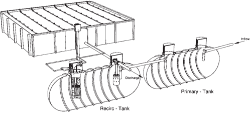
Figure 4-11. Overview schematic of RSF/RGF, without denitrification.
The bottom of the filter starts with a liner and an underdrain that collects the treated wastewater to drain it back to the recirculation tank.
The media in the filter ranges widely in size depending on application, but the size distribution is relatively tight, as discussed earlier. The media shown in Figure 4-12 is less effective as a physical filter, but will provide lower-maintenance biological treatment.
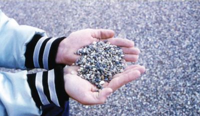
Figure 4-12. Typical media for an RSF/RGF.
Figure 4-13 is a cross section cutaway of an RGF with the full depth of the filter shown in the far rear corner and the entire system exposed in the closest front corner. The details of the distribution manifold are shown in Figure 4-14. In particular, take note of the guards over the distribution holes and the main header manifold feeding the three pipe distribution manifolds.
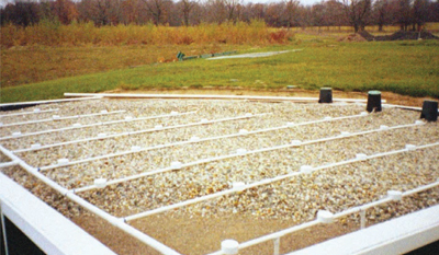
Figure 4-13. RGF cross section cutaway.
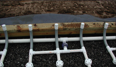
Figure 4-14. RSF distribution manifold for water coming from the recirculation tanks.
Treated water from these systems is generally of very high quality and can usually be used directly for application to an irrigation system.
Operation, Monitoring, and Maintenance Considerations
The first unit in this system is a septic tank. The septic tank must be monitored to determine when it should be pumped to remove accumulated materials. Sludge, water, and scum depth measurements should be taken at the beginning and end of the critical season. The system should be pumped when it is clear that the accumulated material will exceed 30% of the overall tank depth prior to the next measurement. It is critical that the settling function of the septic tank is not disturbed by the recirculation of the nitrified effluent. It is also critical that the dissolved oxygen in the septic tank not rise above 0.25 mg/L due to recirculation of the nitrified effluent, since this has the potential to poison denitrification. Operation is similar to many other nitrogen removal systems. It is necessary to maintain a reasonable recirculation ratio to fully nitrify and then denitrify the effluent. The recirculation ratios are both adjusted between 3:1 and 5:1.
Distal pressure (pressure at the end of the lateral) should be measured once or twice per year. The distal head should typically be in the range of 5 to 8 ft. This is measured using a clear tube that can be screwed in or attached to laterals, allowing easy determination of head; the measurement itself is not as critical as the change over time. A head increase over time may mean clogging of orifices and indicate a need to either brush or power-wash the laterals. The most common means of cleaning laterals is to pass a bristle brush through the pipe and then flush the pipe with water to remove solids. This technique is particularly favored on smaller household RSF systems. In large systems, a power-washer with a 75-ft hose is used to clean the pipes. The lateral ends are removed, the power-washer is passed through the pipe, and the pipe is flushed to remove solids.
Even with regular septic tank pumping and lateral maintenance, it may be necessary to clean the sand or gravel media in the filter. Each system is different, and the required cleaning may range from very labor-intensive and expensive media replacement to a simple operational exercise. If the system is periodically overloaded for a short period of time and there is a limited area that is showing signs of plugging, the cell may be isolated and rested with only occasional dosing. In a seasonally loaded system, it may be desirable to recirculate for an extended period after the season is over to clear all excess biomat out of the system. In a high-strength system with large sand- or gravel-sized media, it is recommended that an aeration system be placed between the support gravel and the media (Figure 4-15). In the event the system is overloaded and plugged, it can be submerged and then aerated to clean out the excess organic material.
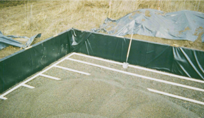
Figure 4-15. The aeration system placed below the media and above support gravel.
In the event of a plugging problem, the outlet of the tank is plugged, the water level is allowed to come up and submerge the media, and the system is aerated until the organic material is degraded (CIDWT, 2008). The microbial biomass is then drained out of the filter to a location suitable for removing the solids. Figure 4-16 illustrates one influent distribution system placed on top of the media. The holes in the distribution pipe point up and emit a jet that impacts the plastic chamber, distributing it on the media.
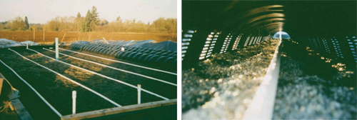
Figure 4-16. High-strength waste RSF/RGF influent distribution system (CIDWT, 2008).
The system pictured in Figure 4-17 served a large grocery store that stripped the wax off the floors and washed the wax and stripper down the floor drains and onto the RSF. The figure shows the system after it had been damaged by wax.
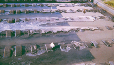
Figure 4-17. RSF damaged by wax and wax stripper discharge onto filter (CIDWT, 2008).
The filter in Figure 4-18 had a built-in aeration system that was used to recover the filter without media removal and replacement. Figure 4-18 shows the aeration system in use. It is clear that it is not an optimal oxygen transfer system, but it was sufficient to recover the RSF from this same type of damage at the hands of two different managers.
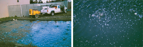
Figure 4-18. Aeration system being operated using a portable compressor (CIDWT, 2008).
The aerated recovery was accomplished in a few days at a cost of $3,000 to $4,000, compared to a cost of $30,000 if the aeration system had not been present. Since the aeration system is a simple PVC pipe network with a few valves, it is an excellent added feature for all high-strength wastewater systems.
Aerobic, Facultative, and Anaerobic Ponds
Lagoons, along with wetlands, are described in the Onsite Wastewater Treatment Systems Manual (U.S. EPA, 2002) as one of the passive aquatic systems. A pond system typically consists of a large earthen basin filled with wastewater undergoing some combination of physical, chemical, and/or biological treatment processes that render the wastewater more acceptable for discharge to the environment. There are a number of types of pond systems: facultative lagoon, aerobic pond system, advanced integrated pond system, and aerated pond system. Ponds can be designed as a full containment (evaporation) pond, an intermittent discharge pond, or a continuous discharge pond. A cross section of a typical pond system is shown in Figure 4-19.

Figure 4-19. Plan view of a typical lagoon.
In many areas, a lagoon is called a wastewater stabilization pond or a facultative lagoon. A facultative lagoon is a pond sufficiently deep (typically 5 to 8 ft, with a maximum depth of 10 ft) to allow organic solids to settle to the bottom as sludge and decay anaerobically, while an aerobic liquid layer forms above the sludge where facultative and aerobic bacteria oxidize the incoming organics and the products of anaerobic sludge decomposition. Ponds are used for the removal of BOD5 and for chemical processes such as nitrification and phosphorous reduction. Because they tend to be relatively large in area and require a substantial buffer zone, in some instances with fencing around the buffer zone, they are not widely used. However, in rural areas with large amounts of available land, lagoons are used fairly frequently for single-family residential and small community situations.
While there are many forms of lagoons (aerobic, anaerobic, facultative), the facultative version is usually used for residential, small commercial, and small community purposes. Facultative lagoons tend to perform best when there are multiple (usually three) cells, but single-cell lagoons are most frequently used for single home residential purposes. Multiple cells help minimize short-circuiting. The systems usually consist of lined basins into which effluent from a septic tank or an aerobic treatment process flows. After many days of retention (20–190), effluent flows out to the next downstream component.
Where the soil doesn’t create a concern, unlined lagoons are sometimes used. Unlined stabilization ponds are fairly common on Tribal lands in New Mexico. It is also common for these systems to be full containment. They are designed as facultative lagoons, but ultimate disposal is by evaporation. When these systems are initially installed as unlined lagoons and then upgraded with a liner, they are frequently too small. The portion of the water that was previously entering the groundwater through the bottom of the pond must now be evaporated. Each upgrade of this nature should be evaluated to determine the need for a surface water or groundwater discharge to disperse the additional treated wastewater effluent. Full treatment with groundwater discharge is preferable to leaking of partially treated wastewater into the groundwater.
Passive aerobic and facultative lagoons obtain oxygen for microbial metabolism from the atmosphere, and combine sedimentation of particulate matter with biological degradation. BOD levels are consistently reduced 75 to 95% in facultative lagoons. The oxygen transfer is balanced with the demand by sizing the system based on a specific area loading. This should be checked if the system is experiencing consistent odor problems. The typical design rate for the first pond is 75 lb BOD/ac/day, and for the entire system is 50 lb/ac/day. This value should be assumed to be a sea level value and should be corrected for elevation by multiplying the area loading by the ratio of oxygen saturation at the elevation of treatment divided by oxygen saturation at sea level. Because lagoons are very conducive to algal growth, the TSS concentrations in the effluent can vary widely, from large increases in TSS in hot seasons to 90% reduction in colder seasons. Total nitrogen reductions can approach 60% and total phosphorous reductions can approach 50%. Algae provide part of the treatment with their uptake of nutrients. Wastewater depth is typically between 3 and 5 ft, with a practical maximum depth of 8 ft in a passive system. The top surface is typically aerobic, and the environment becomes more anaerobic toward the bottom. In a small residential system, a septic tank is usually required prior to the lagoon. In a community system, there is frequently no pretreatment prior to the facultative pond system.
Lagoons require berms (usually with a side slope of 3:1 run to rise, topping out at least 2 ft above the liquid level), fencing (to keep animals out), and a buffer area of 100 ft or more; thus, large areas are required for this technology. There are safety concerns with lagoons. It is crucial that lagoons be properly fenced and secured to prevent access by children and animals. Even if a lagoon is fenced, a lagoon with a plastic liner should provide escape nets, plastic netting that lies on top of the liner and provides a walking surface for operators, pets, or wildlife that fall into the pond. Trees within the buffer zone are removed to maximize the exposure of the lagoon’s surface to sunlight and wind. No deep-rooted vegetation or burrowing animals are allowed to be in the dike area. A prairie dog or gopher hole can cause the loss of an entire dike in a matter of minutes. While a lagoon is relatively low-maintenance, mowing of the berm and fence maintenance are required. Use of livestock to graze the dikes is not acceptable since this frequently results in severe erosion along the pathways used by the livestock. Periodic pumping of the lagoon may be necessary as solids collect over time.
Chapter 5: Mechanical Systems
Advanced Treatment Units
Any treatment beyond a simple septic tank is usually considered advanced treatment. However, there are two distinct types of advanced treatment: mechanical systems and relatively passive natural systems. The previous chapter dealt with passive systems that tend to require less attention on the part of the owner/operator/manager; this chapter will discuss mechanical systems, which require additional attention. In areas under the jurisdiction of the New Mexico Environment Department, advanced onsite wastewater systems, if installed now, must be operated by a registered management entity (RME); this is a national trend. It is suggested that Tribal environmental managers discourage these systems unless a qualified operator can perform operation and maintenance.
Mechanical treatment systems tend to have very close analogs in the large centralized mechanical treatment plants. It should be noted that there are some distinct differences and similarities between these smaller systems and the large centralized systems. Robert Gott (NMSU/WUTAP [Water Utility Technical Advisory Program]) has produced the following table (Table 5-1) comparing large and small systems to assist operational staff in thinking about these systems.
Table 5-1. Differences Between Onsite and Centralized/Municipal Mechanical Wastewater Systems
| Centralized/municipal system characteristics |
| • Analytical laboratory – Process control testing |
| • Plant is reviewed daily |
| • Better O&M program (budget) |
| • Maintenance – Spare parts |
| • Flows are metered |
| • Industrial pre-treatment program |
| • Qualified operator required – Knowledge is beneficial |
| • Backup power |
| • Component flexibility |
| Different types of onsite systems (distributed wastewater treatment, including residential, clusters, and commercial) |
| • Trickling filters |
| • Activated sludge ○ Suspended media ○ Fixed media/activated sludge ○ Aerobic/anoxic |
| Onsite system characteristics |
| • Inspected periodically ○ Quarterly ○ Twice a year ○ Once a year |
| • Generally no spare parts |
| • Disposable mechanical equipment |
| • No component or operating flexibility |
| • Surging problems |
| • Sometimes associated with a septic tank |
| • No backup power |
| • Hydraulic and organic loading is intermittent |
| • Leach field problems |
| • Poorly written O&M manuals |
| Troubleshooting onsite systems |
| • Mechanical checks |
| • DO check in the ATU and septic tank |
| • Solids check ○ Primary/secondary chambers and septic tanks ○ Settleable solids in reactor basin ○ Settleable solids in treated effluent |
| • Microscopic examination of microbes in the reactor basin |
| • Alkalinity checks on the influent and effluent |
| • Dye testing check for hydraulics |
| • Consult homeowner if toxics are entering the plant |
| • Visually examine the drainfield |
| • Test strips or colorimetric kit to check nitrogen levels |
Each type of onsite system has strengths and weaknesses; the objective in selecting a system is to identify which set of strengths are optimized in a given situation without suffering unduly from the system weaknesses. Most mechanical systems have a smaller system footprint and are capable—with an excellent operator—of higher treatment efficiency. In general, though, they consume more energy and the process is easier to upset.
Activated Sludge/Aerobic Treatment Unit (ATU)
An aerobic treatment unit (ATU) might be thought of as a small-scale activated sludge process. The ATU is typically used in lieu of a septic tank or in series with a septic or trash tank (small septic tank, less than 1/2–1/3 the size of a regular septic tank), though some employ an aeration device inserted into a regular septic tank. The ATU provides treatment of wastewater using aerobic decomposition processes and is often a suspended growth system, such as activated sludge, which implies that the microbes performing the treatment are suspended in the water being treated. Other pretreatment processes that use aerobic decomposition and occur in an unsaturated state are included with “media filters” and are fixed film systems. Fixed film implies that the treatment microbes are attached to a solid surface and the contaminated water flows past the microbes. The ATU produces significant reductions of BOD, TSS, and microorganisms, though there is still a significant risk of pathogens.
The ATU usually consists of a concrete, fiberglass, or polyethylene tank, with or without a preceding trash tank. It is beneficial for all ATUs to be preceded by a full-size septic tank, regardless of the manufacturer’s recommendation. Most ATUs have the following subcomponents (see Figure 5-1):
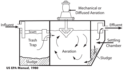
Figure 5-1. Cross section of generic ATU.
- A trash trap to remove larger solids. Units without an integrated trash trap may require that one be placed in front of the unit.
- An aeration chamber that provides dissolved oxygen and wastewater constituents (food) to the aerobic microorganisms. This mixture of dissolved oxygen, wastewater constituents, and microorganisms is called mixed liquor. Aeration and mixing occur by one of the following mechanisms:
- Mechanical aeration—A propeller-like device, or the impeller of a pump, draws in air from the atmosphere and injects it into the mixed liquor by its spinning action.
- Diffuser—A porous ceramic device or a plastic manifold containing small holes through which air is injected under pressure from a blower or compressor. The size of the air bubbles will vary depending on the type of mechanism used. Typically, the smaller the bubbles, the greater the amount of oxygen that can dissolve in the liquid.
- Airlift pump—A small-diameter pipe through which air is injected by a blower or compressor. The small pipe, surrounded by a larger-diameter pipe (riser tube), is inserted a distance below the top surface of the mixed liquor. When air is discharged from the small pipe it rises rapidly, creating a chimney effect and bringing with it mixed liquor from lower in the aeration chamber. In the riser tube, oxygen is transferred from the bubbles to the mixed liquor. There is usually a splash plate above the mixed liquor surface that helps mix and aerate the rising air and mixed liquor. The pumping rate is very sensitive to the amount of lift required; a small increase in the amount of lift will dramatically reduce the pumping rate and therefore the aeration efficiency.
- Rotating biological contactor—The fixed media is on a drum or disks partially submerged in the mixed liquor. The disks rotate slowly, and microorganisms on the media are aerated when they are above the liquid surface. This option will be discussed later.
- A settling or clarification chamber that allows settling and/or filtration of biological cells and other solids to provide a clarified effluent. The clarification or settling chamber may be a separate chamber immediately following the aeration chamber, as shown in Figure 5-1, or it may be located within the aeration chamber or totally outside the ATU unit. Filters or effluent screens may substitute for or be used in combination with a clarification chamber in some units, but this should be done with caution. Since the clarifier is needed to remove the bulk of the solids, the screen should be used as a polishing device, not as the primary solid separation device because it has very little ability to store solids.
In the aeration chamber, dissolved oxygen, microorganisms, and wastewater are combined using some combination of mechanisms. The aeration chamber contains some means of injecting air into the liquid. The smaller the air bubbles, the more surface area is available for oxygen to be dissolved by the liquid, and the higher the transfer efficiency. In an activated sludge system, the treatment microorganisms in the mixed liquor are suspended in the water. Most of the small systems are passively activated; that is, they do not have a sludge recycle pump and instead recycle by gravity flow. The small ATUs are designed to have uniform mixing throughout the aeration chamber. The ATU systems provide more efficient treatment than a septic tank, but can be difficult to operate and require more maintenance. Aerobic treatment unit systems are usually considered where there are environmentally sensitive lots, extreme soils (fine or coarse), high-strength waste, a shallow limiting layer (groundwater, fractured bedrock), or a small lot size.
Fixed film (attached growth) systems tend to be more stable than suspended growth systems. In a fixed film system, the microbes grow on a solid surface, such as the one shown in Figure 5-2. The media filters discussed in Chapter 4 used a fixed film process with periodic wetting of microbial biomass; these included sand filters and attached growth systems similar to the trickling filter. The systems discussed here have been arbitrarily classed as ATUs, which is a small activated sludge plant, rather than media filters. In a typical activated sludge plant, the microbes that treat the wastewater are suspended in the water column by the aeration and digest the nutrients in the water. Both the fixed film activated sludge and periodically submerged media systems have similarities to both ATUs and media filter systems. The fixed film activated sludge has both suspended microorganisms and microorganisms fixed on the surface of a medium. These systems appear to be unique to the smaller (less than 10,000 gpd) proprietary systems. The periodically submerged, or dosed, systems are analogous to the trickling filters and rotating biological contactors in large system applications. A trickling filter is a type of fixed film filter that provides aerobic treatment of the wastewater. Wastewater influent is evenly dispersed so that wastewater flows in a thin layer (sheet) over the media filter. A biological film grows on the media and sloughs off periodically to renew itself; biofilm that has broken off collects at the bottom of the media bed. When a trickling filter is used for BOD5 removal, efficiency is increased through recirculation of the treated effluent back onto the filter.
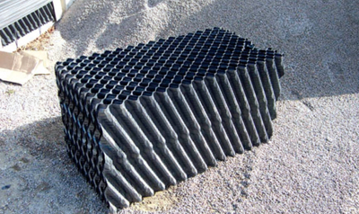
Figure 5-2. Example of structured fixed growth media.
The fixed film activated sludge technologies are a combination of suspended growth microbes (e.g., activated sludge) and fixed film microbes (e.g., trickling filter). The fixed film portion of the microbial biomass is grown on both structured media and random dump media. The structured media is usually used in trickling filters. This type of ATU has principles of operation very similar to media filters. The primary differences compared to a suspended growth aerobic treatment unit are
- the fixed growth media is usually submerged below the liquid level and
- some mechanical means of aerating the effluent is used.
Most ATUs designed to serve small to medium applications use a fixed growth media incorporating a combination of fixed growth and suspended growth. It is common in these systems for the suspended microorganism mass to be greater than the attached microorganism mass. The advantage of the attached growth organisms is that they are not easily upset, so if the suspended organisms are impaired the attached organisms act as a seed for more organisms and provide continued treatment.
Another major class of fixed film reactor is the rotating biological contactor (RBC) shown in Figure 5-3. The fixed media consist of disks mounted on a drive shaft with a drive motor on the end of the shaft. The drive shaft rotates the disks, alternately exposing portions of the disks to the atmosphere and to the wastewater. Some units inject air into the liquid below the disks. This helps prevent overgrowth of the biological material on the discs and ensures that the liquid phase remains aerobic. This supplemental air is highly recommended.
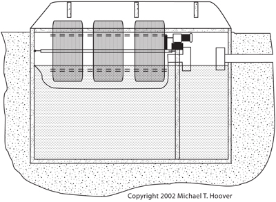
Figure 5-3. Typical rotating biological contactor (RBC).
ATU Flow Schemes/Sequencing Batch Reactor (SBR)
Continuous flow is usually referred to as demand flow since the actual flow is intermittent due to wastewater generation patterns within the structure; when wastewater flows in, some effluent flows out, like in a conventional septic tank. Most ATUs processing small flows use this flow mode. Figure 5-1 depicts an example of this.
A sequencing batch reactor (SBR) is shown in Figure 5-4. The SBR is sometimes called a periodic process or time dose process. They have historically been activated sludge units, though variations have been developed that use attached growth. The time dose requires a pre-equalization strategy of some kind. There are actually two kinds of SBRs, intermittent inflow or true batch SBR and continuous inflow SBR. The true batch SBR accepts influent only at specified intervals. A unit or volume of influent usually goes sequentially through each of the five steps of this process: fill, react, settle, draw, and idle. The time frames for each step vary according to the specific product being used.
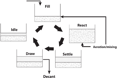
Figure 5-4. Flow sequence for a sequencing batch reactor (SBR).
The reactor is closed to inflow during the treatment cycle, which requires a parallel intermittent flow unit or a large storage chamber prior to the treatment unit from which liquid is periodically dosed to the SBR. The unit shown in Figure 5-5 is a true batch SBR.
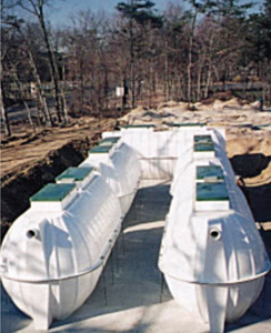
Figure 5-5. Commercially available true batch SBR system.
In a continuous inflow SBR, the influent can flow continuously during all phases of the treatment cycle, even though the actual flow will be intermittent due to wastewater generation patterns. To reduce short-circuiting, a partition is normally added to the tank to separate the turbulent aeration zone from the quiescent area.
Aerobic treatment units come in a variety of mechanical configurations and sizes and incorporate a variety of mechanical and non-mechanical methods to enhance the aerobic biodegrading of wastewater. The ATUs are processes similar to the secondary treatment processes used in public wastewater treatment plants, but have been downsized for use with smaller flows. Like their cousins at public wastewater treatment plants, ATUs are designed for specific hydraulic and biological loading rates. Unlike the larger aerobic treatment plants, most ATUs do not routinely receive flows of consistent quantity and quality, nor do they have adequate continuous operational staffing. These are major causes of stress for ATUs. Most have been developed to treat domestic-strength wastewater, which means they may have marginal aeration systems for high-strength wastes. Anticipated waste strength must be considered when selecting a unit, and several ATUs have been developed specifically for higher-strength wastes. Some, like certain SBRs, are available in packaged configuration for small community or cluster applications.
Pre-treatment in the form of a trash trap/tank or septic tank, either external or internal, should be required with all ATUs. Treatment performance and stability may be improved using a time-dosed submersible effluent pump, located in an external trash tank, to dose the ATU. This will help overcome the disadvantages posed by the variable quantity and quality of the influent. The trash tank is then, in effect, a pre-treatment equalization basin.
Final treatment/dispersal components that follow ATUs may have sizing and location requirements that differ from those following septic tanks due to the higher quality of effluent that is expected.
The National Sanitation Foundation (NSF) has developed Standard 40, which serves as the protocol for certifying and listing of ATU products that meet specific performance standards. Standard 40 is used to test ATU products that treat a minimum of 400 gpd and up to 1,500 gpd of wastewater. The testing protocol provides for two different classes of performance. Class I units are expected to perform to secondary standards: carbonaceous BOD (CBOD5) of 25 mg/L over a 30-day average and TSS of 30 mg/L over a 30-day average. It is important to understand that the NSF performance is the best anticipated performance and can only be achieved with adequate operation and maintenance. Standard 40 does not include a standard for fecal coliform; ATUs cannot be expected to remove more than 2 logs of fecal coliform, though there is considerable variability. Ongoing operation, monitoring, and maintenance by competent, trained personnel are especially crucial with these systems. The NSF Standard 45 serves as the protocol for certifying and listing products that meet specific performance standards for removing nitrogen from the wastewater rather than BOD.
Chapter 6: Disinfection
Disinfection is the last treatment process before dispersing effluent into the environment. The purpose of disinfection is to destroy pathogens and microorganisms in the treated wastewater by either killing them or by preventing their replication. Disinfection is not sterilization since it only reduces the bacterial count to a designated level. Disinfection is accomplished using either 1) a chemical agent, such as chlorine, ozone, or iodine; 2) a physical agent, such as heat; or 3) irradiation, such as ultraviolet (UV) radiation. The two techniques used primarily in onsite wastewater treatment are chlorination and UV radiation; both methods bring the effluent into direct contact with the disinfection agent.
Disinfection requires adequately treated effluent with a low solids concentration. There are a number of variables that control how effective the disinfection process will be, including
- the concentration (chemical) or intensity (irradiation) of the disinfecting agent,
- the contact or exposure time,
- the number and types of organisms that are to be destroyed,
- wastewater characteristics (temperature, pH, TSS, BOD5),
- ammonia and other nitrogen compounds (NO3, NO2) that affect chlorination, and
- uniformity of the disinfecting agent’s exposure to the microorganisms.
Disinfection is used for onsite wastewater treatment where the site conditions (primarily soils that are too coarse and/or shallow) indicate there may be a potential for contamination of ground or surface waters by bacteria. It is also used for rare surface applications or surface water discharges to minimize the public’s potential exposure to pathogens. Any kind of wastewater reuse (e.g., purple pipe watering of landscape plants or toilet flushing using treated wastewater) will require disinfection of the wastewater.
Chlorination
Chlorination, when used on a small scale, is typically done in a chamber called a stack feeder, or with a small liquid feed system using a liquid chlorine tank and a pump. The chlorine stack feeder is the most common in residential onsite wastewater systems (see Figures 6-1 and 6-2). The stack feeder contains calcium hypochlorite tablets, and the effluent is exposed to the chlorine in the tablets as it moves through the stack. For medium-scale systems, liquid chlorine is becoming fairly common. Oxidizable material must be considered since it will exhibit a chlorine demand and minimize the effect of the chlorination.
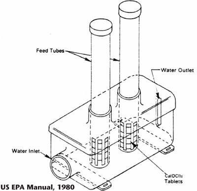
Figure 6-1. Typical chlorine stack feeder.
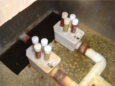
Figure 6-2. Chlorine stack feeder system.
The pH of the effluent will determine which species of chlorine will be used as the primary disinfectant. Chlorine is a more effective disinfectant when the pH is slightly acidic. Fortunately, effluent from onsite wastewater components is typically neutral to slightly acidic. If ammonia is present, chlorine will combine with the ammonia to form chloramines that are less effective disinfecting agents, but which have a longer life. With septic systems, most of the nitrogen will be in ammonia form. With aerobic units, nitrogen-based constituents range from mostly ammonia to all nitrate depending on unit sizing.
A contact time of 30 to 45 minutes with the chlorine is desirable. Thus, a contact chamber should be immediately downstream from the chlorination unit. Many systems that use chlorine disinfection today do not have sufficient contact time to properly disinfect. Chlorine will typically have a residual disinfecting effect; if this is not desired, tablets that dechlorinate or take the chlorine out of the effluent can be used. These are placed downstream of the chlorine contact chamber in a stack feeder similar to the one shown in Figure 6-1. Dechlorination should not occur until sufficient contact time with the chlorine has occurred.
Some pathogens are not readily affected by normal concentrations of chlorine, including giardia and cryptosporidium (especially the cysts). Tablet chlorinator performance problems include overdosing or underdosing due to tablet uniformity and tablet feed problems. Consequently, there is a need for frequent inspection, correction, and replenishment of tablets. Inspections must ensure the tablets are neither stuck in the stack feeder nor eroded through the stack feeder’s flow channel, allowing effluent to pass without contacting the chlorine tablets. The biggest problem with chlorine tablet feeders is that homeowners simply forget to keep tablets in the feeder.
Ultraviolet Disinfection
Ultraviolet disinfection is typically a simple flow-through pipe containing an ultraviolet tube, as shown in Figures 6-3 and 6-4.
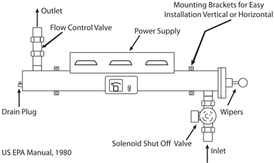
Figure 6-3. Schematic of typical ultraviolet unit.
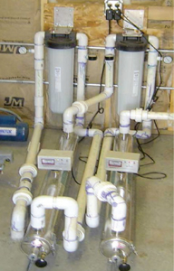
Figure 6-4. Ultraviolet unit.
Ultraviolet rays are used to irradiate pathogens, disabling an organism’s ability to reproduce by disrupting its DNA/RNA. Wavelengths between 250 and 265 nanometers are most effective at destroying pathogens. Low-pressure mercury lamps are typically used to disinfect small flows with UV. Because glass blocks UV rays, ultraviolet tubes are usually made of fused silica or quartz. Some UV units use a Teflon tube around the UV bulb to keep it from getting dirty or fouled by wastewater, while others use mechanical wipers to clean the surface. The unit shown in Figure 6-4 has mechanical wipers.
There are a number of factors that influence the effectiveness of UV disinfection, and precaution should be taken to prevent a reduction in efficiency. Suspended solids can provide “hiding” places for microorganisms. Solids and certain chemicals can also absorb UV rays, minimizing their intensity and effectiveness. Bulbs must be periodically cleaned, depending on water quality and manufacturer’s instructions, to maximize exposure of the microorganisms to the UV rays. Bulbs must also be replaced periodically (usually annually) because the intensity of the desired wavelength range will decrease over time; UV intensity can become unacceptable even though the bulb still glows, and an intensity meter must therefore be used.
To guarantee appropriate contact time, each unit has a maximum number of gallons per minute that can pass through the UV unit. For single-family residential units, this maximum flow is typically between 5 and 10 gpm (as noted by the manufacturer). There is some evidence that suggests microorganisms may repair themselves if they are immediately exposed to sunlight following UV irradiation. The solution to this is to keep the effluent in the dark after irradiation by putting it into the soil or into a contact chamber. If the water alkalinity is in excess of 120 mg/L as CaCO3, UV systems will require significantly more chemical cleaning to reduce precipitation buildup on the bulbs.
Ozone
Ozone has been suggested as a disinfectant, but is seldom used in small-scale systems. It has many advantages, but the technology required to produce the ozone is the largest disadvantage. It takes significant energy to produce an adequate concentration of oxidant, and the production of ozone is very sensitive to the amount of water in the air used to produce the ozone. Although these are sometimes available, they are not a good option for an onsite wastewater system.
Water reuse falls under a number of major categories, including graywater, purple pipe water, and indirect potable reuse. Each of these categories has specific requirements and concerns.
Chapter 7: Reuse and Conservation of Wastewater
Water reuse falls under a number of major categories, including graywater, purple pipe water, and indirect potable reuse. Each of these categories has specific requirements and concerns.
Graywater
Graywater is the lowest water quality and is usually divided into residential graywater and commercial graywater. Residential graywater is wastewater from laundry, bathtubs, showers, and bath skinks. For additional information concerning the application of graywater, contact the New Mexico Office of the State Engineer. Rules and regulations for residential graywater systems in New Mexico changed in 2003 with new state laws. These new rules make it possible and feasible for the general public to use their graywater for landscape irrigation. A graywater reuse system can be as simple as moving the washing machine to the back porch and using the rinse water from the washing machine to water the apple tree. Commercial systems can be very sophisticated; readers should refer to the “Uniform Plumbing Code.”
Purple Pipe Water
Purple pipe water is wastewater that has been treated to a level specified by a regulatory body and determined to be acceptable for reuse; the specified treatment level is typically a function of the intended use and reflects public health and safety concerns. For example, New Mexico has five classes of non-potable above-ground reuse, each of which requires specific quality levels for the intended reuse. Under the state of New Mexico’s jurisdiction, any above-ground wastewater reuse must meet the purple pipe requirements.
Wastewater Reuse Regulations
Tribal governments must decide which wastewater reuse methods will be most beneficial. In the arid Southwest, with water appropriation issues and drought stress, there are great advantages to reusing treated wastewater. Aside from obvious sources like rainwater, multiple use of treated wastewater is the only source of truly new water in most arid southwestern jurisdictions, both now and in the foreseeable future. The EPA has developed and published “Guidelines for Water Reuse” (EPA/625/R-04/108, September 2004) in order to help utilities and regulatory authorities understand, evaluate, and make the best possible use of reclaimed waters. The requirements for various use classes adopted by the state of New Mexico will be discussed here as an example of the approach taken by one group of professionals. These are not regulations and have not gone through the important discussions between stakeholder groups that are required when regulations are created. In spite of this shortcoming, they are similar to other regulations adopted around the country and will provide a basis for discussion.
Unrestricted urban reuse under the NMED Groundwater Division’s above-ground reuse guidelines is the use of reclaimed water where public exposure is likely to occur. States require a minimum of secondary treatment and disinfection before distribution onto public lands. Additional treatment is frequently required, with many government jurisdictions requiring the equivalent of California Code of Regulations Title 22.
Restricted urban reuse is the use of reclaimed water where public exposure is controlled; it requires a minimum of secondary treatment or biological treatment followed by disinfection prior to reuse.
Under appropriate circumstances, both restricted and unrestricted urban reuse water may be used for watering parks, fields, golf courses, or other green spaces. Secondary treated and disinfected effluent may be used for toilet flushing or fire suppression in some jurisdictions. Both restricted and unrestricted urban reuse require a water reclamation facility, reclaimed water distribution system (including storage and pumping facilities), and dual distribution systems to separately distribute both reclaimed and regular water.
The daily irrigation demand for reclaimed water can be estimated from an inventory of the total irrigable acreage to be served by the reclaimed water system and the estimated weekly irrigation rates. An estimate of irrigation demand to evaluate potential value of reclaimed water can also be made by analyzing local water production records and noting seasonal changes.
In settings where water is extremely valuable, it may be advantageous to perform a detailed analysis of reclaimed water supply and usage demand. Figure 7-1 illustrates that seasonal use of irrigation water may outstrip the available reused water supply on a straight demand basis. Some jurisdictions have used aquifer storage and recovery to “bank” treated wastewater during the winter for extraction and use during the summer.
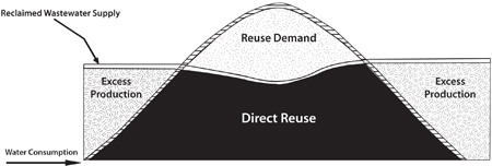
Figure 7-1. This figure illustrates the seasonal demand, a combination of the direct reuse and the reuse from stored water. These can be balanced by storing or "banking" water during low direct use periods. Reclaimed water supply is the middle line that represents advanced treated wastewater, which is produced year-round at a relatively uniform rate.
Agricultural Reuse
Agricultural reuse for food crops usually requires a high level of treatment for edible foods. Some states require that edible foods irrigated with reused wastewater be processed and cooked.
Agricultural reuse for non-food crops often simply requires secondary treatment followed by disinfection.
Groundwater Recharge
Groundwater recharge or aquifer storage and recovery (ASR) is probably the fastest-growing area of high-quality water reuse. The purposes of recharging groundwater are to provide additional treatment for future reuse, augment potable and non-potable waters, provide storage of reclaimed water for subsequent retrieval and reuse, and control or prevent ground subsidence. Aquifer storage and recovery systems are being used in a number of states to overcome seasonal imbalances in both potable and reclaimed water projects. The use of ASR, either for irrigation or for indirect potable reuse, should be restricted to larger, sophisticated utilities. Each individual utility that considers this option must decide if they have the cash flow and management structure to support an activity of this nature. The absolute minimum treatment for aquifer storage and recovery is secondary treatment with advanced solids removal and disinfection. Once the water is treated, there are a number of methods for recharging the aquifer, as shown in Table 7-1, and each has strengths and weaknesses. The most efficient methods are also the most expensive and difficult to manage. The three most common methods are recharge basins, vadose zone injection wells, and direct injection wells.
Table 7-1. Comparison of Major Engineering Factors for Engineered Groundwater Recharge
| Recharge Basins | Vadose Zone Injection Wells | Direct Injection Wells | |
| Aquifer Types | Unconfined | Unconfined | Unconfined or Confined |
| Pretreatment Requirements | Low Technology | Removal of Solids | High Technology |
| Estimated Major Capital Costs | Land and Distribution System | $25,000–75,000 per well | $500,000–1,500,000 per well |
| Capacity | 100–20,000 m3/hectare/day |
1,000–3,000 m3/hectare/day/well |
2,000–6,000 m3/hectare/day/well |
| Maintenance Requirements | Drying and Scraping | Drying and Disinfection | Disinfection and Flow Reversal |
| Estimated Life Cycle | >100 years | 5–20 years | 25–50 years |
| Soil Aquifer Treatment | Vadose Zone and Saturated Zone | Vadose Zone and Saturated Zone | Saturated Zone |
| Source: U.S. EPA Guidelines for Water Reuse, 2004 | |||
Recharge basins are simply large, unlined basins with sufficient head to allow water to move quickly to at least 3 ft deep.
Vadose zone injection wells are commonly 6 ft (2 m) in diameter and 100 to 150 ft (30–46 m) deep and are backfilled with porous media. A riser pipe is used to allow water to enter at the bottom of the injection well to prevent air entrainment.
Direct injection involves pumping reclaimed water directly into the groundwater (saturated) zone, which is usually a well-confined aquifer. Direct injection is used where groundwater is deep or where hydrogeological conditions are not conducive to surface spreading. Such conditions might include unsuitable soils of low permeability, unfavorable topography for construction of basins, the desire to recharge confined aquifers, scarcity of land, or unacceptable evaporative losses.
Limitations of Groundwater Recharge
While there are obvious advantages associated with groundwater recharge, there are several possible limitations (Oaksford, 1985):
- Extensive land areas may be needed for spreading basins.
- Costs for treatment, water quality monitoring,and injection/infiltration facilities operations may be prohibitive.
- Recharge may increase the danger of aquifer contamination due to inadequate or inconsistent treatment prior to injection. This is a major concern.
- Differences in water chemistry may cause plugging of the aquifer and injection well screen, resulting in a loss of both aquifer functionality and very expensive wells.
- Not all recharged water may be recoverable due to movement beyond the extraction well capture zone or mixing with poor-quality groundwater.
- Hydrogeologic uncertainties, such as transmissivity, faulting, and aquifer geometry, may reduce the effectiveness of the recharge project in meeting water supply demand.
- Inadequate institutional arrangements or groundwater laws may not protect water rights and may present liability and other legal problems. The degree to which these factors might limit implementation of a groundwater recharge system is a function of the severity of the site-specific impediments balanced against the need to protect existing water sources or expand raw water supplies.
Note that indirect potable reuse is not recommended for any small- or medium-size systems at this time since the management burden will be, out of necessity, extreme.
The following is an excerpt from the New Mexico code illustrating an example of regulations regarding injection wells (New Mexico Environment Department). The ASR wells are covered by this guidance. On Tribal land they are directly under EPA’s Safe Drinking Water Act (SDWA) Programs Underground Injection Well Program. It is interesting to note that this is also the Federal guidance for large (>2,000 gpd) septic system liquid dispersal systems.
20.6.2.5002 Underground Injection Control well Classifications
A. Underground injection control wells include the following.
- Any dug hole or well that is deeper than its largest surface dimension, where the principal function of the hole is emplacement of fluids.
- Any septic tank or cesspool used by generators of hazardous waste, or by owners or operators of hazardous waste management facilities, to dispose of fluids containing hazardous waste.
- Any subsurface distribution system, cesspool or other well which is used for the injection of wastes.
B. Underground injection control wells are classified as follows:
- Class I wells inject fluids beneath the lowermost formation that contains 10,000 milligrams per liter or less TDS. Class I hazardous or radioactive waste injection wells inject fluids containing any hazardous or radioactive waste as defined in 74-4-3 and 74-4A-4 NMSA 1978, including any combination of these wastes. Class I non-hazardous waste injection wells inject non-hazardous and non-radioactive fluids, and they inject naturally-occurring radioactive material (NORM) as provided by Section 20.3.1.1407 NMAC.
- Class II wells inject fluids associated with oil and gas recovery.
- Class III wells inject fluids for extraction of minerals or other natural resources, including sulfur, uranium, metals, salts or potash by in situ extraction. This classification includes only in situ production from ore bodies that have not been conventionally mined. Solution mining of conventional mines such as stopes leaching is included in Class V.
- Class IV wells inject fluids containing any radioactive or hazardous waste as defined in 74-4-3 and 74-4A-4 NMSA 1978, including any combination of these wastes, above or into a formation that contains 10,000 mg/L or less TDS.
- Class V wells inject a variety of fluids and are those wells not included in Class I, II, III or IV. Types of Class V wells include, but are not limited to, the following:
- a. Domestic liquid waste injection wells
- i. domestic liquid waste disposal wells used to inject greater than 2,000 gallons per day of treated domestic liquid waste through subsurface fluid distribution systems or vertical wells;
- ii. septic system wells used to emplace greater than 2,000 gallons per day of domestic liquid waste into the subsurface, which are comprised of a septic tank and subsurface fluid distribution system;
- iii. large capacity cesspools used to inject greater than 2,000 gallons per day of domestic liquid waste, including drywells that sometimes have an open bottom and/or perforate sides.
- b. Industrial waste injection wells
- i. air conditioning return flow wells used to return to the supply aquifer the water used for heating or cooling;
- ii. dry wells used for the injection of wastes into a subsurface formation;
- iii. geothermal energy injection wells associated with the recovery of geothermal energy for heating, aquaculture and production of electrical power;
- iv. stormwater drainage wells used to inject storm runoff from the surface into the subsurface;
- v. motor vehicle waste disposal wells that receive or have received fluids from vehicular repair or maintenance activities;
- car wash waste disposal wells used to inject fluids from motor vehicle washing activities.
- c. Mining injection wells
- i. stopes leaching wells used for solution mining of conventional mines;
- ii. brine injection wells used to inject spent brine into the same formation from which it was withdrawn after extraction of halogens or their salts;
- iii. backfill wells used to inject a mixture of water and sand, mill tailings or other solids into mined out portions of subsurface mines whether water injected is a radioactive waste or not;
- iv. injection wells used for in situ recovery of lignite, coal, tar sands, and oil shale.
- d. Ground water management injection wells
- i. ground water remediation injection wells used to inject contaminated ground water that has been treated to ground water quality standards;
- ii. in situ ground water remediation wells used to inject a fluid that facilitates vadose zone or ground water remediation.
- iii. recharge wells used to replenish the water in an aquifer, including use to reclaim or improve the quality of existing ground water;
- barrier wells used to inject fluids into ground water to prevent the intrusion of saline or contaminated water into ground water of better quality;
- subsidence control wells (not used for purposes of oil or natural gas production) used to inject fluids into a non-oil or gas producing zone to reduce or eliminate subsidence associated with the overdraft of fresh water;
- wells used in experimental technologies.
- e. Agricultural injection wells - drainage wells used to inject fluids into ground water to prevent the intrusion of saline or contaminated water into ground water of better quality.
- a. Domestic liquid waste injection wells
Acknowledgments
This manual was produced by New Mexico State University in an effort to create a better understanding of wastewater management to assist Tribal communities in creating a framework to protect their public health, and to make training available for wastewater operators and installers that allows them to operate their distributed wastewater systems to the best of that system’s capability.
This document was a collaborative project involving numerous organizations. Most of the contribution to the development of this manual came from the Consortium of Institutes for Decentralized Wastewater Treatment (CIDWT) and other individual institutions. This document drew heavily on the CIDWT curriculums for Universities, Practitioners, and Operation and Maintenance. The CIDWT efforts are gratefully acknowledged. Development of this manual involved extensive research, input, and numerous hours of work. However, this course is still limited in scope, and anyone interested in a deeper understanding of operation and maintenance of distributed wastewater treatment systems should seriously consider the O&M course offered by CIDWT. This manual provides a good foundation for the depth course offered by CIDWT, which is a 16-contact-hour course dedicated solely to O&M training.
We wish to extend a special thanks to the individuals and organizations that made up the Onsite Wastewater Tribal Advisory Committee for their assistance:
- Michael Alvidrez, Utility Director, Santa Ana Pueblo
- Kenny Lovato, Environmental Director, Pueblo of Santo Domingo
- Captain Russ Pederson, Director, Indian Health Services
- Heather Hummelberger, Director, New Mexico Environmental Finance Center
- Robert Todd, Groundwater/UIC Project Manager, U.S. Environmental Protection Agency
References
Brown, R.B. 2003. Soil texture [Fact Sheet SL-29]. Gainesville: University of Florida Cooperative Extension Service.
Burks, B.D., and M.M. Minnis. 1994. Onsite wastewater treatment systems. Madison, WI: Hogarth House, Ltd.
Consortium of Institutes for Decentralized Wastewater Treatment. 2006. Residential onsite wastewater treatment systems: An operation and maintenance service provider program. Ames, IA: Midwest Plan Service, Iowa State University.
Consortium of Institutes for Decentralized Wastewater Treatment. 2008. Analyzing Wastewater Treatment Systems. B. Lesikar, W. Stuth, Sr., R. Melton, C. O’Neill, D. Gustafson, M. Lee, G. Loomis, and D. Kalen. AgriLifeExtension, TAMU System. College Station, Texas.
Crites, R., and G. Tchobanoglous. 1998. Small and decentralized wastewater management systems. Boston: WCB/McGraw-Hill.
Gritzuk, M. 2003. The importance of water reuse in the 21st century. Presentation to the Subcommittee on Water & Power Committee on Resources, U.S. House of Representatives, March 27, 2003.
Gustafson, D., J. Anderson, A. Amoozegar, and D.L. Lindbo. 2005. Water movement and soil treatment text. In D.L. Lindbo and N.E. Deal (Eds.), Model decentralized wastewater practitioner curriculum, National Decentralized Water Resources Capacity Development Project. Raleigh: North Carolina State University.
Hoover, M., and T. Konsler. 2004. Soil facts: Septic systems and their maintenance [AG-439-13]. Raleigh: North Carolina State University Cooperative Service.
Indian Health Service, Office of Environmental Health and Engineering. 2009. Public law 86-121 July 31, 1959, 50th anniversary report. Washington, D.C.: U.S. Department of Health and Human Services.
Lenning, D., T. Banathy, D. Gustafson, B.J. Lesikar, S. Wecker, and D. Wright. 2005. Technology overview text. In D.L. Lindbo and N.E. Deal (Eds.), Model decentralized wastewater practitioner curriculum, National Decentralized Water Resources Capacity Development Project. Raleigh: North Carolina State University.
Lindbo, D.L., M. Stolt, R. Miles, D. Mokma, S. Greene, and M. Hoover. 2005. Soil module text. In D.L. Lindbo and N.E. Deal (Eds.), Model decentralized wastewater practitioner curriculum, National Decentralized Water Resources Capacity Development Project. Raleigh: North Carolina State University.
New Mexico Environment Department. 20.6.2.5002. 2001
Oaksford, E.T. 1985. Artificial recharge: Methods, hydraulics, and monitoring. In T. Asamo (Ed.), Artificial recharge of groundwater (pp. 69–127). Boston: Butterworth Publishers.
Protection of Environment, 40 C.F.R. § 146.5. 2010.
Soil Survey Division Staff. 1993. Soil survey manual [USDA Handbook 18]. Washington, D.C.: USDA–Natural Resources Conservation Service, Soil Survey Division.
Trotta, P.D., D.L. Lindbo, and J.O. Ramsey. 2005. Site and soil evaluation text. In M.A. Gross and N.E. Deal (Eds.), University curriculum development for decentralized wastewater management, National Decentralized Water Resources Capacity Development Project. Fayetteville: University of Arkansas.
U.S. Department of the Interior, Bureau of Reclamation. 2003. Water 2025: Preventing conflict and crisis in the West. Washington, D.C.: Author.
U.S. Environmental Protection Agency. n.d. Drilling waste management information system [Online]. http://web.ead.anl.gov/dwm/regs/federal/epa/index.cfm
U.S. Environmental Protection Agency. 1976. National interim primary drinking water regulations [EPA 570/9-76-003]. Washington, D.C.: Author.
U.S. Environmental Protection Agency. 1980. Onsite wastewater treatment and disposal systems design manual [EPA/625/1-80-012]. Washington, D.C.: Author.
U.S. Environmental Protection Agency. 1999. Wastewater technology fact sheet: Sequencing batch reactor [EPA 832-F-99-073]. Washington, D.C.: Author.
U.S. Environmental Protection Agency. 2001. Federal water quality standards for Indian country: Proposed rule. Washington, D.C.: Author. Available from https://water.epa.gov/scitech/swguidance/standards/upload/2008_05_16_tribes_proposedcore2001.pdf.
U.S. Environmental Protection Agency. 2002. Onsite wastewater treatment systems manual [EPA/625/R-00/008]. Washington, D.C.: Author.
U.S. Environmental Protection Agency. 2003. When is a septic system regulated as a Class V well? Washington, D.C.: Author.
U.S. Environmental Protection Agency. 2004. Guidelines for water reuse [EPA/625/R-04/108]. Washington, D.C.: Author.
U.S. Environmental Protection Agency. 2005. Handbook for managing onsite and clustered (decentralized) wastewater treatment systems [No. 832-B-05-001]. Cincinnati: U.S. EPA National Service Center for Environmental Publications.
United Nations Secretariat, Population Division, Department of Economic and Social Affairs. 2001. World urbanization prospects: The 1999 revision [ST/ESA/SER.A/194]. New York: Author.
World Heath Organization. n.d. Water sanitation and health (WSH). Available from https://www.who.int/water_sanitation_health/en.
Disclaimers
CIDWT Disclaimer
These materials are the collective effort of individuals from academic, regulatory, and private sectors of the onsite/decentralized wastewater industry. These materials have been peer-reviewed and represent the current state of knowledge/science in this field. They were developed through a series of writing and review meetings with the goal of formulating a consensus on the materials presented. These materials do not necessarily reflect the views and policies of the Consortium of Institutes for Decentralized Wastewater Treatment (CIDWT). The mention of trade names or commercial products does not constitute an endorsement or recommendation for use from these individuals or entities, nor does it constitute criticism for similar ones not mentioned.
NDWRCDP Disclaimer
This work was supported by the National Decentralized Water Resources Capacity Development Project (NDWRCDP) with funding provided by the U.S. Environmental Protection Agency through a Cooperative Agreement (WPA No. X-830851-01-0) with Water Environment Research Foundation (WERF) in Alexandria, Virginia. These materials have not been reviewed by the U.S. Environmental Protection Agency, NDWRCDP, or WERF. The contents of these materials do not necessarily reflect the views and policies of the NDWRCDP, WERF, or the U.S. Environmental Protection Agency, nor does the mention of trade names or commercial products constitute their endorsement or recommendation for use.
1Funded by the U.S. Environmental Protection Agency.
Note from New Mexico State University: This curriculum has been modified from the original to satisfy the requirements for this course. Chapters 1 and 7 are the exceptions, and have been written to benefit its readers.
To find more resources for your business, home, or family, visit the College of Agricultural, Consumer and Environmental Sciences on the World Wide Web at pubs.nmsu.edu.
Contents of publications may be freely reproduced for educational purposes. All other rights reserved. For permission to use publications for other purposes, contact pubs@nmsu.edu or the authors listed on the publication.
New Mexico State University is an equal opportunity/affirmative action employer and educator. NMSU and the U.S. Department of Agriculture cooperating.
Printed and electronically distributed February 2013, Las Cruces, NM.


