A Simple Flow Measuring Device for Farms1
Water Task Force: Report 3
Zohrab Samani, Henry Magallanez, and Rhonda Skaggs
College of Agricultural, Consumer and Environmental Sciences, New Mexico State University
Authors: Respectively, Department of Civil and Geological Engineering, College of Engineering, New Mexico State University; District Engineer, Elephant Butte Irrigation District; and Department of Agricultural Economics and Agricultural Business, College of Agricultural and Home Economics, New Mexico State University.
Introduction
The objective of this publication is to provide a guideline for construction and operation of a simple water measuring device for open channels. In recent years, southern New Mexico has faced serious drought conditions. The water allotment in the Elephant Butte Irrigation District (EBID) for the 2003 irrigation season was eight acre-inches per acre. The average seasonal water requirement for pecans and alfalfa in the area served by EBID is 4.5 to 5 ft. There is an urgent need for additional sources of irrigation water, but this is not usually possible and is cost prohibitive. An effective irrigation water conservation plan which includes water measurement will help improve efficiency and make best use of limited water supplies.
The first step in developing an on-farm water conservation plan is to establish how much water is being delivered to fields. When water is over applied, the excess water leaches below the root zone of the crop without additional benefit to the crop. A small amount of excess water (<10%) is needed to leach out the salt. Excess water can also reduce yield, due to leaching of nutrients and waterlogging of fields with heavy clay soils. On the other hand, under application of water, especially during critical growth periods, can result in yield losses. Currently less than 1% of farmers in the Elephant Butte Irrigation District have installed water measuring devices (Magallanez, 2003).
This publication will describe the construction, installation and operation of a simple and inexpensive flow measurement device (commonly called a flume), which can be constructed using metal or plywood and a small piece of PVC pipe.
If the flume is built, installed and operated correctly, the device will provide a very accurate measurement of the flow, comparable with other flow-measuring devices such as the Parshall Flume (U.S. Bureau of Reclamation, 1984) or RBC (Bos et al., 1984) with the added advantages of low cost and simple construction.
Construction
The device is the S-M flume (Samani and Magallanez, 2000). The flume consists of a rectangular section of duct contracted from both sides by vertical PVC or metal pipe. The cross section of the channel is restricted using half sections of PVC or metal pipe as shown in fig. 1 (top view). The side view of the flume is shown in fig. 2.
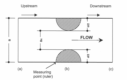
Figure 1. Top view of S-M flume
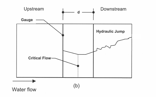
Figure 2. Side view of S-M flume
The central, narrow section of the flume (Bc) is the throat. The ratio of the throat width to the width of the rectangular channel (B) is the contraction ratio. The contraction ratio (Bc/B) should be more than 0.40 (40%). The purpose of the contraction is to create a critical flow, which makes it possible to calculate the flow of water by simply measuring the depth of the water at the upstream corner of the PVC pipe (as indicated in fig. 1). Instructions for building, installing and operating the flume follow.
Building the Flume
- Measure the maximum depth of the water in the channel. The height of the flume should be equal to maximum depth of the water in the channel.
- Calculate the length of the flume (a-c, fig. 1). This length should be equal to 1.5 times the height of the flume.
- Install the PVC or metal pipes 2/3 of the distance from the upstream entrance of water into the flume. For example, if the maximum depth of the water is 2 ft, the height of the flume is 2 ft, and the length would be 3 ft. The distance from the center of the contracting pipe (i.e., the vertically positioned PVC or metal pipe) to the upstream entrance (a-b, fig. 1) would be 2 ft, and the distance from the center of the vertically positioned PVC or metal pipe to downstream end (b-c, fig. 1) would be 1 foot. The values given here for the length, downstream and upstream, are minimum requirements. If the lengths are longer, it will not affect the measurement results.
- Cut the pipe into equal halves lengthwise. In fig. 1, the measurement d is equal to the PVC or metal pipe's diameter, and d/2 illustrates the equally split pipe halves.
- The rectangular section of the flume can be constructed from plywood, steel or aluminum sheets. Plywood construction is useful for short-term flow measurement, but will not last long. Steel would be more appropriate for permanent measurement. If the flume is to be moved, aluminum construction is best since it provides a light device that can be easily transported.
- A water-measuring ruler (gauge) needs to be installed at the upstream corner of the pipe as shown in fig. 1.
- The vertically positioned PVC or metal pipe can also function as a stilling well. A perforation can be drilled at the upstream corner of the pipe to convert the PVC pipe into a stilling well. A stilling well can be used to measure the flow depth either manually or electronically using a pressure transducer and data logger.
- The PVC pipe is attached to the wall using a strip of metal which is wrapped around the pipe and bolted to the wall in both ends. The ruler (gauge) is attached to the pipe using epoxy glue.
- Metal cross-bars can be placed over the top of the flume in order to stabilize the walls during and after installation.
Installing the Flume
- The flume should be leveled both laterally and lengthwise within the channel where it is installed.
- The area surrounding the flume and underneath the flume needs to be sealed with soil or other material such as concrete, such that the entire water flow can pass through the flume and not undermine the flume's leveled position in the channel.
Operating the Flume
- The depth of water in the flume is measured at the point indicated in fig.1 to measure the flow of water through the channel.
- The relationship between the depth of the water in the flume and the discharge rate (or flow of water through the flume) is as follows:
Q = 0.701(√g )(Bc)0.91(H)1.59
- Variables in the equation above are defined as:
Q = flow rate in m3/sec or ft3/sec (m = meter, ft = feet, sec = seconds)
g = acceleration of gravity, 9.81 m/sec2 (SI unit) or 32.2 ft/sec2 in English units.
Bc = flume throat width in meters (SI unit) or feet in English units
H = depth of the water flow at the gauge, in meters (SI unit) or feet in English units.
- The discharge rate can be calculated in SI unit or in English unit. For example, if H is measured as 0.5 ft, in a flume with throat width (Bc) equal to 2 ft, then the discharge rate from the above equation can be calculated as:
Q = 0.701*(√32.2)*(20.91)*(0.51.59) = 2.483 cfs
Where: cfs = cubic feet per second
- Once the flume is built, the flume equation can be used to generate a rating table consisting of two columns, which shows the relationship between H and Q.
- In order for the flume to operate correctly, it has to be under free flow condition. This means that depth of the water at the downstream end of the flume (point c in fig. 1) divided by the depth of the water at the gauge should be less than 0.85 (85%). If the ratio is more than 0.85, the bottom of the flume must be raised in order to reduce the depth ratio. This adjustment is normally done only once, when the flume is installed.
- The side view of the flume shown in fig. 2 illustrates the movement of water as it flows through the flume. The ruler (gauge) is positioned so as to measure the water at the upstream junction of the flume wall and the vertically positioned pipe. The flow of water at the ruler is the critical depth, which is the same as the depth of water inside the stilling well. If the depth is measured at the ruler, there is normally some turbulence which causes the depth to move up and down. In such a case, an average depth should be used to calculate the flow. It is recommended to measure the depth inside the stilling well to avoid error caused by water level fluctuations. Distance d is again the diameter of the vertically positioned PVC or metal pipe. The hydraulic jump is a temporary turbulence in the water as it moves out of the flume and goes back to the normal depth in the channel.
An Installed S-M Flume
Figures 3 and 4 are pictures of S-M flumes currently being used to measure flows in New Mexico. Fig. 3 shows a S-M flume installed in an open channel in a dirt ditch in an acequia in Santa Fe. The flume is made of aluminum and is 2 ft wide and 3 ft long. The S-M flume in fig. 4 is installed at a turnout from a concrete lined ditch in La Union. This flume is constructed of steel (including the vertical pipe halves) and is 1.5 ft wide and 4 ft long. Concrete has been poured at the junction of the flume and the canal in order to stabilize the flume and prevent the water from bypassing the flume.
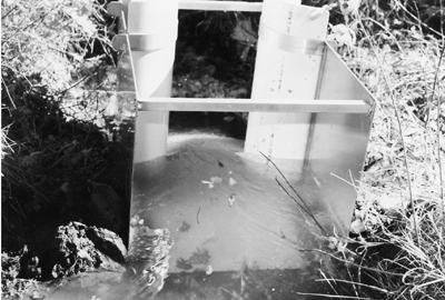
Figure 3. S-M flume installed in an acequia in Santa Fe, N.M.
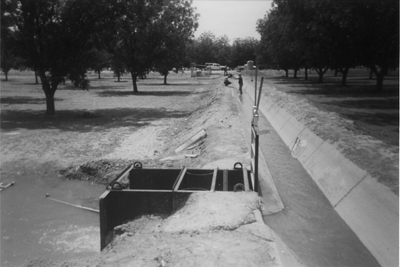
Figure 4. S-M flume installed in turnout on a pecan farm in La Union, N.M.
Footnotes
1A project paper from the Rio Grande Basin Initiative. RGBI is a joint Texas A&M/NMSU Project, administered in New Mexico by the NMSU Water Task Force. (Back to top)
References
Bos, M.G, J.A. Replogle, A.J. Clemens. 1984. Flow Measuring Flumes for Open Channel Systems. John Wiley & Sons, Inc., New York, New York.
Magallanez, H., 2003. District Engineer, Elephant Butte Irrigation District. Personal communication.
Samani, Z. and Magallanez, H. 2000. "Simple Flume for Flow Measurement in Open Channel." American Society of Civil Engineers (ASCE) Journal of Irrigation and Drainage 126(2):127-129.
United States Bureau of Reclamation. 1984. Water Measurement Manual. U.S. Dept. of Interior, Denver.
To find more resources for your business, home, or family, visit the College of Agricultural, Consumer and Environmental Sciences on the World Wide Web at aces.nmsu.edu
Contents of publications may be freely reproduced for educational purposes. All other rights reserved. For permission to use publications for other purposes, contact pubs@nmsu.edu or the authors listed on the publication.
New Mexico State University is an equal opportunity/affirmative action employer and educator. NMSU and the U.S. Department of Agriculture cooperating.
March 2005